Toyota 4Runner: System Diagram
Toyota 4Runner Service Manual / Vehicle Interior / Seat / Front Power Seat Control System(w/ Memory) / System Diagram
SYSTEM DIAGRAM
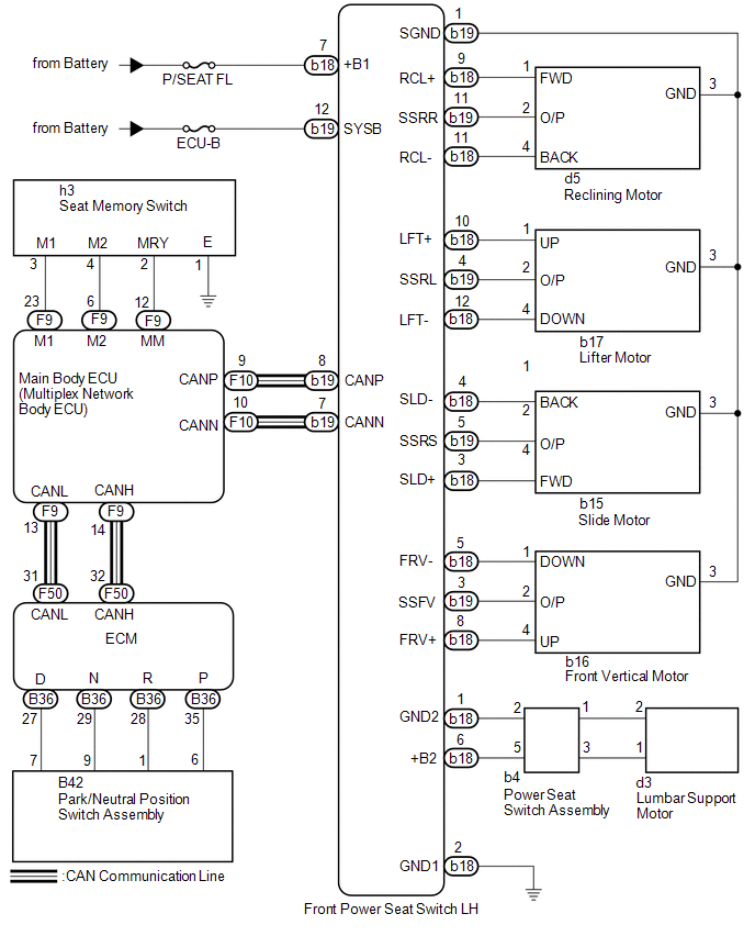 Communication Table
|
Sender |
Receiver |
Signal |
Line |
|---|---|---|---|
|
ECM |
Main Body ECU (Multiplex Network Body ECU) |
|
CAN |
|
Main Body ECU (Multiplex Network Body ECU) |
Front Power Seat Switch LH |
|
CAN |
 System Description
SYSTEM DESCRIPTION
1. FRONT POWER SEAT CONTROL SYSTEM DESCRIPTION
The driver seat is equipped with slide, reclining, lifter, front vertical
and lumbar support adjustment functions.
Th ...
 How To Proceed With Troubleshooting
CAUTION / NOTICE / HINT
HINT:
Use the following procedure to troubleshoot the front power seat control
system.
*: Use the Techstream.
PROCEDURE
1.
VEHI ...
Other materials about Toyota 4Runner:
Air Inlet Damper Control Servo Motor Circuit (B1442)
DESCRIPTION
The recirculation damper servo sub-assembly sends pulse signals to inform the
No. 1 air conditioning amplifier assembly of the damper position. The No. 1 air
conditioning amplifier assembly activates the motor (normal or reverse) based on
th ...
Installation
INSTALLATION
PROCEDURE
1. INSTALL NO. 1 ULTRASONIC SENSOR RETAINER
(a) Align the keyhole and protrusion as shown in the illustration.
Text in Illustration
*1
Keyhole
...
© 2016-2026 | www.to4runner.net

0.0204
0.0204