Toyota 4Runner: System Diagram
Toyota 4Runner Service Manual / Drivetrain / Axle And Differential / Differential System / System Diagram
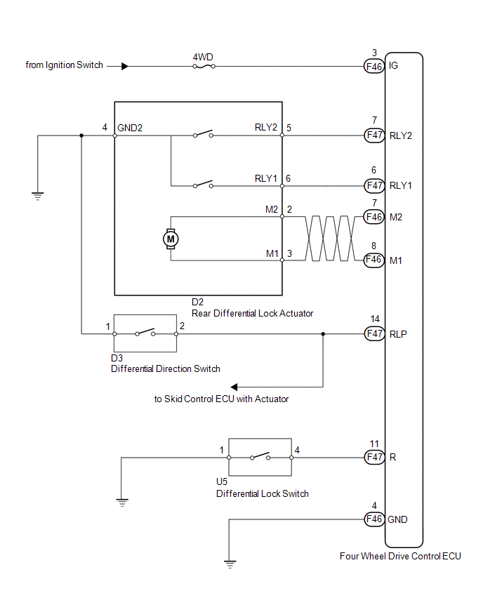
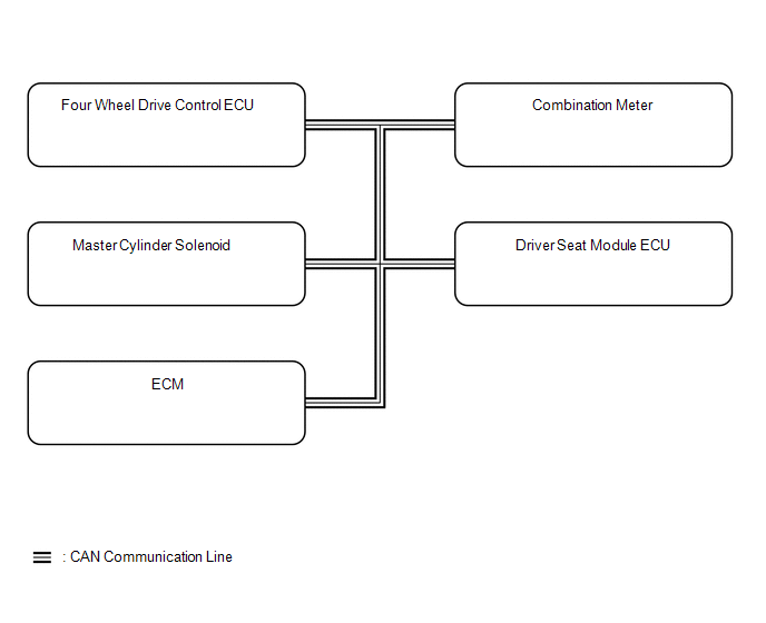
SYSTEM DIAGRAM
 Precaution
PRECAUTION
1. IGNITION SWITCH EXPRESSION
HINT:
The type of ignition switch used on this model differs according to the specifications
of the vehicle. The expressions listed in the table below are ...
 Problem Symptoms Table
PROBLEM SYMPTOMS TABLE
HINT:
Use the table below to help determine the cause of problem symptoms.
If multiple suspected areas are listed, the potential causes of the symptoms
are lis ...
Other materials about Toyota 4Runner:
Disassembly
DISASSEMBLY
CAUTION / NOTICE / HINT
PROCEDURE
1. REMOVE OUTER MIRROR LH
(a) Put protective tape around the outer mirror LH.
(b) Using a moulding remover, detach the 2 claws of the outer mirror
LH as shown in the illustration.
Text in Ill ...
Acceleration Sensor Internal Circuit (C1419,C1435)
DESCRIPTION
The skid control ECU receives signals from the yaw rate and acceleration sensor
via the CAN communication system.
The yaw rate and acceleration sensor has a built-in acceleration sensor and detects
the vehicle condition using 2 circuits (GL1, ...
© 2016-2026 | www.to4runner.net

0.0105
0.0105