Toyota 4Runner: Terminals Of Ecu
TERMINALS OF ECU
1. CHECK MAIN BODY ECU (MULTIPLEX NETWORK BODY ECU) AND DRIVER SIDE JUNCTION BLOCK ASSEMBLY
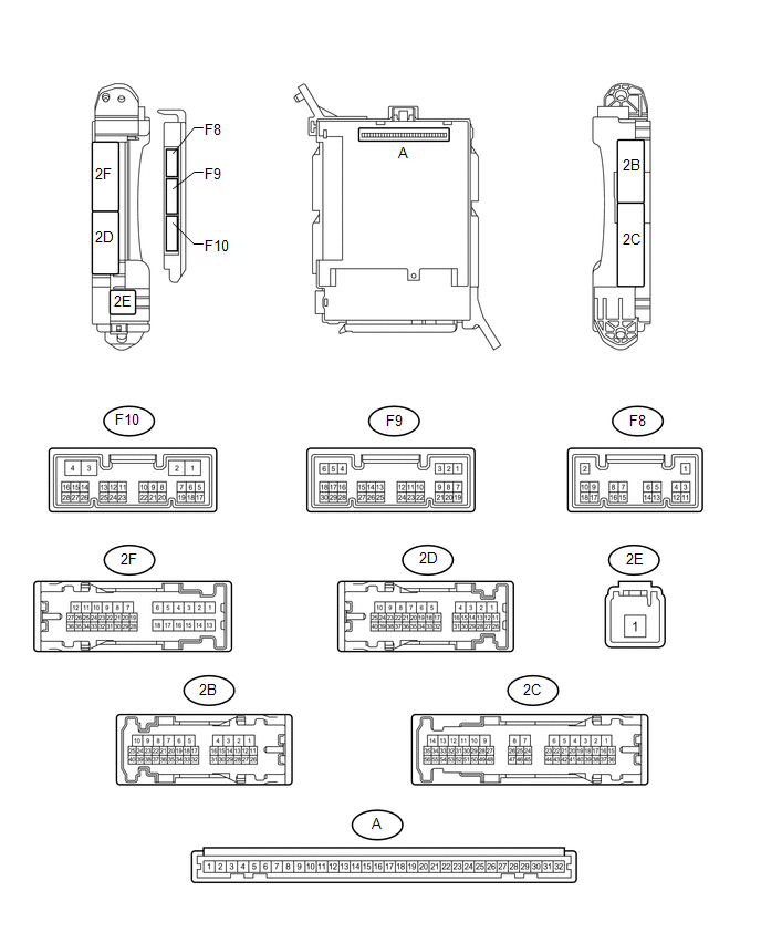
(a) Remove the main body ECU (multiplex network body ECU) from the driver side
junction block assembly (See page .gif) ).
).
(b) Measure the resistance and voltage according to the value(s) in the table below.
|
Terminal No. (Symbol) |
Wiring Color |
Terminal Description |
Condition |
Specified Condition |
|---|---|---|---|---|
|
F10-3 (GND2) - Body ground |
W-B - Body ground |
Ground |
Always |
Below 1 Ω |
|
A-11 (GND1) - Body ground |
None - Body ground |
Ground |
Always |
Below 1 Ω |
|
A-30 (BECU) - Body ground |
None - Body ground |
Battery power supply |
Always |
11 to 14 V |
|
A-32 (IG) - Body ground |
None - Body ground |
IG power supply |
Ignition switch ON |
11 to 14 V |
If the result is not as specified, there may be a malfunction on the wire harness side.
2. CHECK MULTIPLEX NETWORK MASTER SWITCH ASSEMBLY
(a) Disconnect the h1 multiplex network master switch assembly connector.
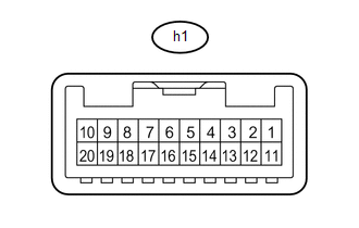
(b) Measure the resistance and voltage according to the value(s) in the table below.
|
Terminal No. (Symbol) |
Wiring Color |
Terminal Description |
Condition |
Specified Condition |
|---|---|---|---|---|
|
h1-12 (GND) - Body ground |
W-B - Body ground |
Ground |
Always |
Below 1 Ω |
|
h1-11 (B) - Body ground |
G - Body ground |
Battery power supply |
Always |
11 to 14 V |
If the result is not as specified, there may be a malfunction on the wire harness side.
3. CHECK FRONT POWER WINDOW REGULATOR MOTOR ASSEMBLY LH
(a) Disconnect the I2 front power window regulator motor assembly LH connector.
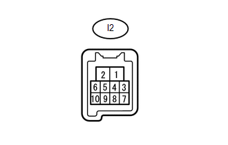
(b) Measure the resistance and voltage according to the value(s) in the table below.
|
Terminal No. (Symbol) |
Wiring Color |
Terminal Description |
Condition |
Specified Condition |
|---|---|---|---|---|
|
I2-1 (GND) - Body ground |
W-B - Body ground |
Ground |
Always |
Below 1 Ω |
|
I2-2 (B) - Body ground |
R - Body ground |
Battery power supply |
Always |
11 to 14 V |
If the result is not as specified, there may be a malfunction on the wire harness side.
4. CHECK FRONT POWER WINDOW REGULATOR MOTOR ASSEMBLY RH
(a) Disconnect the H2 front power window regulator motor assembly RH connector.
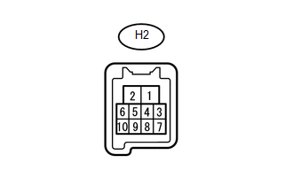
(b) Measure the resistance and voltage according to the value(s) in the table below.
|
Terminal No. (Symbol) |
Wiring Color |
Terminal Description |
Condition |
Specified Condition |
|---|---|---|---|---|
|
H2-1 (GND) - Body ground |
W-B - Body ground |
Ground |
Always |
Below 1 Ω |
|
H2-2 (B) - Body ground |
G - Body ground |
Battery power supply |
Always |
11 to 14 V |
If the result is not as specified, there may be a malfunction on the wire harness side.
5. CHECK REAR POWER WINDOW REGULATOR MOTOR ASSEMBLY LH
(a) Disconnect the K2 rear power window regulator motor assembly LH connector.

(b) Measure the resistance and voltage according to the value(s) in the table below.
|
Terminal No. (Symbol) |
Wiring Color |
Terminal Description |
Condition |
Specified Condition |
|---|---|---|---|---|
|
K2-1 (GND) - Body ground |
W-B - Body ground |
Ground |
Always |
Below 1 Ω |
|
K2-2 (B) - Body ground |
W - Body ground |
Battery power supply |
Always |
11 to 14 V |
If the result is not as specified, there may be a malfunction on the wire harness side.
6. CHECK REAR POWER WINDOW REGULATOR MOTOR ASSEMBLY RH
(a) Disconnect the J2 rear power window regulator motor assembly RH connector.
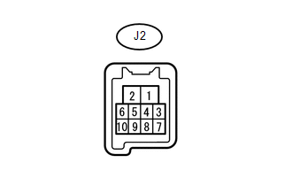
(b) Measure the resistance and voltage according to the value(s) in the table below.
|
Terminal No. (Symbol) |
Wiring Color |
Terminal Description |
Condition |
Specified Condition |
|---|---|---|---|---|
|
J2-1 (GND) - Body ground |
W-B - Body ground |
Ground |
Always |
Below 1 Ω |
|
J2-2 (B) - Body ground |
W - Body ground |
Battery power supply |
Always |
11 to 14 V |
If the result is not as specified, there may be a malfunction on the wire harness side.
7. CHECK SLIDING ROOF ECU (SLIDING ROOF DRIVE GEAR SUB-ASSEMBLY) (w/ Sliding Roof System)
(a) Disconnect the S10 sliding roof ECU (sliding roof drive gear sub-assembly) connector.
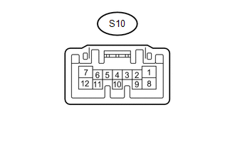
(b) Measure the resistance and voltage according to the value(s) in the table below.
|
Terminal No. (Symbol) |
Wiring Color |
Terminal Description |
Condition |
Specified Condition |
|---|---|---|---|---|
|
S10-12 (E) - Body ground |
W-B - Body ground |
Ground |
Always |
Below 1 Ω |
|
S10-8 (B) - Body ground |
W - Body ground |
Battery power supply |
Always |
11 to 14 V |
|
S10-1 (IG) - Body ground |
L - Body ground |
IG power supply |
Ignition switch ON |
11 to 14 V |
If the result is not as specified, there may be a malfunction on the wire harness side.
8. CHECK CERTIFICATION ECU (SMART KEY ECU ASSEMBLY) (w/ Smart Key System)
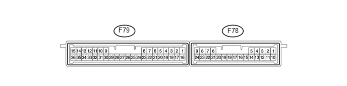
(a) Disconnect the F79 certification ECU (smart key ECU assembly) connector.
(b) Measure the resistance and voltage according to the value(s) in the table below.
|
Terminal No. (Symbol) |
Wiring Color |
Terminal Description |
Condition |
Specified Condition |
|---|---|---|---|---|
|
F79-15 (E) - Body ground |
W-B - Body ground |
Ground |
Always |
Below 1 Ω |
|
F79-1 (+B) - Body ground |
V - Body ground |
Battery power supply |
Always |
11 to 14 V |
|
F79-16 (IG) - Body ground |
W - Body ground |
IG power supply |
Ignition switch ON |
11 to 14 V |
If the result is not as specified, there may be a malfunction on the wire harness side.
9. CHECK POWER MANAGEMENT CONTROL ECU (w/ Smart Key System)
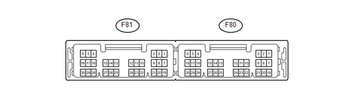
(a) Disconnect the F80 power management control ECU connector.
(b) Measure the resistance and voltage according to the value(s) in the table below.
|
Terminal No. (Symbol) |
Wiring Color |
Terminal Description |
Condition |
Specified Condition |
|---|---|---|---|---|
|
F80-6 (GND) - Body ground |
W-B - Body ground |
Ground |
Always |
Below 1 Ω |
|
F80-5 (GND2) - Body ground |
W-B - Body ground |
Ground |
Always |
Below 1 Ω |
|
F80-1 (AM22) - Body ground |
B - Body ground |
Battery power supply |
Always |
11 to 14 V |
|
F80-2 (AM21) - Body ground |
B - Body ground |
Battery power supply |
Always |
11 to 14 V |
10. CHECK ID CODE BOX (IMMOBILIZER CODE ECU) (w/ Smart Key System)
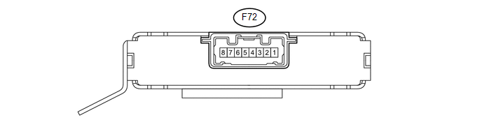
(a) Disconnect the F72 ID code box (immobilizer code ECU) connector.
(b) Measure the resistance and voltage according to the value(s) in the table below.
|
Terminal No. (Symbol) |
Wiring Color |
Terminal Description |
Condition |
Specified Condition |
|---|---|---|---|---|
|
F72-8 (GND) - Body ground |
W-B - Body ground |
Ground |
Always |
Below 1 Ω |
|
F72-1 (+B) - Body ground |
V - Body ground |
Battery power supply |
Always |
11 to 14 V |
If the result is not as specified, there may be a malfunction on the wire harness side.
11. CHECK STEERING LOCK ECU (STEERING LOCK ACTUATOR ASSEMBLY) (w/ Smart Key System)
(a) Disconnect the F68 steering lock ECU (steering lock actuator assembly) connector.
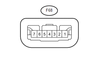
(b) Measure the resistance and voltage according to the value(s) in the table below.
|
Terminal No. (Symbol) |
Wiring Color |
Terminal Description |
Condition |
Specified Condition |
|---|---|---|---|---|
|
F68-1 (GND) - Body ground |
W-B - Body ground |
Ground |
Always |
Below 1 Ω |
|
F68-6 (IG2) - Body ground |
W - Body ground |
IG power supply |
Ignition switch ON |
11 to 14 V |
|
F68-7 (B) - Body ground |
GR - Body ground |
Battery power supply |
Always |
11 to 14 V |
If the result is not as specified, there may be a malfunction on the wire harness side.
12. CHECK AIR CONDITIONING AMPLIFIER ASSEMBLY

(a) Disconnect the F42 air conditioning amplifier assembly connector.
(b) Measure the resistance and voltage according to the value(s) in the table below.
|
Terminal No. (Symbol) |
Wiring Color |
Terminal Description |
Condition |
Specified Condition |
|---|---|---|---|---|
|
F42-14 (GND) - Body ground |
W-B - Body ground |
Ground |
Always |
Below 1 Ω |
|
F42-1 (IG+) - Body ground |
L - Body ground |
IG power supply |
Ignition switch ON |
11 to 14 V |
|
F42-21 (B) - Body ground |
V - Body ground |
Battery power supply |
Always |
11 to 14 V |
If the result is not as specified, there may be a malfunction on the wire harness side.
13. CHECK HEATER CONTROL ASSEMBLY
(a) Disconnect the F29 heater control assembly connector.
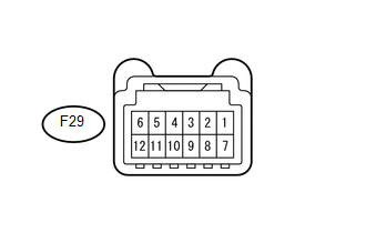
(b) Measure the resistance and voltage according to the value(s) in the table below.
|
Terminal No. (Symbol) |
Wiring Color |
Terminal Description |
Condition |
Specified Condition |
|---|---|---|---|---|
|
F29-11 (GND) - Body ground |
W-B - Body ground |
Ground |
Always |
Below 1 Ω |
|
F29-4 (IG+) - Body ground |
L - Body ground |
IG power supply |
Ignition switch ON |
11 to 14 V |
If the result is not as specified, there may be a malfunction on the wire harness side.
14. CHECK MULTIPLEX NETWORK DOOR ECU (BACK DOOR P/W)
(a) Disconnect the V2 multiplex network door ECU (back door P/W) connector.
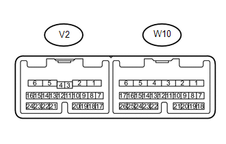
(b) Measure the resistance and voltage according to the value(s) in the table below.
|
Terminal No. (Symbol) |
Wiring Color |
Terminal Description |
Condition |
Specified Condition |
|---|---|---|---|---|
|
V2-6 (GND) - Body ground |
W-B - Body ground |
Ground |
Always |
Below 1 Ω |
|
V2-7 (BECU) - Body ground |
L - Body ground |
Battery power supply |
Always |
11 to 14 V |
|
V2-8 (SIG) - Body ground |
G - Body ground |
IG power supply |
Ignition switch ON |
11 to 14 V |
If the result is not as specified, there may be a malfunction on the wire harness side.
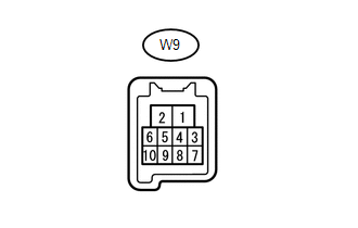
15. CHECK BACK DOOR POWER WINDOW REGULATOR SUB-ASSEMBLY
(a) Disconnect the W9 back door power window regulator sub-assembly connector.
(b) Measure the resistance and voltage according to the value(s) in the table below.
|
Terminal No. (Symbol) |
Wiring Color |
Terminal Description |
Condition |
Specified Condition |
|---|---|---|---|---|
|
W9-1 (GND) - Body ground |
LG - Body ground |
Ground |
Always |
Below 1 Ω |
|
W9-2 (B) - Body ground |
GR - Body ground |
Battery power supply |
Always |
11 to 14 V |
If the result is not as specified, there may be a malfunction on the wire harness side.
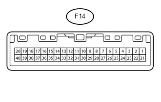
16. CHECK COMBINATION METER ASSEMBLY
(a) Disconnect the F14 combination meter assembly connector.
(b) Measure the resistance and voltage according to the value(s) in the table below.
|
Terminal No. (Symbol) |
Wiring Color |
Terminal Description |
Condition |
Specified Condition |
|---|---|---|---|---|
|
F14-20 (E1) - Body ground |
W-B - Body ground |
Ground |
Always |
Below 1 Ω |
|
F14-15 (B) - Body ground |
L - Body ground |
Battery power supply |
Always |
11 to 14 V |
|
F14-17 (IG+) - Body ground |
R - Body ground |
IG power supply |
Ignition switch ON |
11 to 14 V |
If the result is not as specified, there may be a malfunction on the wire harness side.
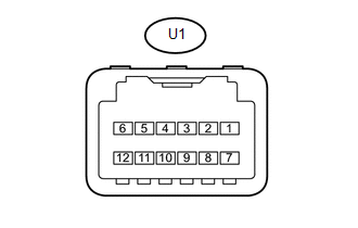
17. CHECK DRIVE MONITOR SWITCH (w/ CRAWL Control)
(a) Disconnect the U1 drive monitor switch connector.
(b) Measure the resistance and voltage according to the value(s) in the table below.
|
Terminal No. (Symbol) |
Wiring Color |
Terminal Description |
Condition |
Specified Condition |
|---|---|---|---|---|
|
U1-7 (GND) - Body ground |
W-B - Body ground |
Ground |
Always |
Below 1 Ω |
|
U1-6 (+B) - Body ground |
L - Body ground |
Battery power supply |
Always |
11 to 14 V |
|
U1-12 (IG) - Body ground |
G - Body ground |
IG power supply |
Ignition switch ON |
11 to 14 V |
If the result is not as specified, there may be a malfunction on the wire harness side.
 Problem Symptoms Table
PROBLEM SYMPTOMS TABLE
HINT:
Use the table below to help determine the cause of problem symptoms.
If multiple suspected areas are listed, the potential causes of the symptoms
are lis ...
 Dtc Check / Clear
DTC CHECK / CLEAR
1. CHECK DTC
(a) Connect the Techstream to the DLC3.
(b) Turn the ignition switch to ON.
(c) Turn the Techstream on.
(d) Enter the following menus: Body Electrical / (desired sy ...
Other materials about Toyota 4Runner:
Rear Speed Sensor RH Malfunction (C1403,C1273,C1274,C1404)
DESCRIPTION
Refer to DTCs C1401 and C1402 (See page ).
DTC Code
DTC Detection Condition
Trouble Area
C1403
C1404
One of the following conditions is met:
At a vehicle speed of 10 k ...
Problem Symptoms Table
PROBLEM SYMPTOMS TABLE
HINT:
Use the table below to help determine the cause of problem symptoms.
If multiple suspected areas are listed, the potential causes of the symptoms
are listed in order of probability in the "Suspected Area" ...

0.0072