Toyota 4Runner: Terminals Of Ecu
TERMINALS OF ECU
1. CHECK DRIVER SIDE JUNCTION BLOCK ASSEMBLY AND MAIN BODY ECU (MULTIPLEX NETWORK BODY ECU)
.png)
(a) Remove the main body ECU (multiplex network body ECU) (See page
.gif) ).
).
(b) Measure the voltage and resistance according to the value(s) in the table below.
|
Terminal No. (Symbol) |
Wiring Color |
Terminal Description |
Condition |
Specified Condition |
|---|---|---|---|---|
|
A-30 (BECU) - Body ground |
- |
Battery power supply |
Always |
11 to 14 V |
|
A-31 (ALTB) - Body ground |
- |
Battery power supply |
Always |
11 to 14 V |
|
A-32 (IG) - Body ground |
- |
Ignition switch power supply |
Ignition switch ON |
11 to 14 V |
|
A-32 (IG) - Body ground |
- |
Ignition switch power supply |
Ignition switch off |
Below 1 V |
|
A-29 (ACC) - Body ground |
- |
ACC power supply |
Ignition switch ACC |
11 to 14 V |
|
A-29 (ACC) - Body ground |
- |
ACC power supply |
Ignition switch off |
Below 1 V |
|
A-11 (GND1) - Body ground |
- |
Ground |
Always |
Below 1 Ω |
|
F10-3 (GND2) - Body ground |
W-B - Body ground |
Ground |
Always |
Below 1 Ω |
If the result is not as specified, there may be a malfunction in the wire harness.
(c) Install the main body ECU (multiplex network body ECU).
(d) Measure the voltage according to the value(s) in the table below.
|
Terminal No. (Symbol) |
Wiring Color |
Terminal Description |
Condition |
Specified Condition |
|---|---|---|---|---|
|
F10-8 (RWSW) - Body ground |
P - Body ground |
Rear washer switch input |
Ignition switch ON, rear washer switch on |
Below 1 V |
|
F10-8 (RWSW) - Body ground |
P - Body ground |
Rear washer switch input |
Ignition switch ON, rear washer switch off |
Pulse generation (See waveform 1 or 2) |
|
F10-17 (RWLS) - Body ground |
R- Body ground |
Rear wiper switch input |
Ignition switch ON, rear wiper switch INT |
Below 1 V |
|
F10-17 (RWLS) - Body ground |
R - Body ground |
Rear wiper switch input |
Ignition switch ON, rear wiper switch off |
Pulse generation (See waveform 1 or 2) |
|
F9-1 (RWC1) - Body ground |
B - Body ground |
Rear wiper switch input |
Ignition switch ON, rear wiper switch LO |
Below 1 V |
|
F9-1 (RWC1) - Body ground |
B- Body ground |
Rear wiper switch input |
Ignition switch ON, rear wiper switch off |
Pulse generation (See waveform 1 or 2) |
|
F8-2 (BW) - Body ground |
B - Body ground |
Rear washer relay operation output |
Ignition switch ON, rear wiper switch on |
Below 1 V |
|
F8-2 (BW) - Body ground |
B - Body ground |
Rear washer relay operation output |
Ignition switch ON, rear wiper switch off |
11 to 14 V |
If the result is not as specified, the main body ECU (multiplex network body ECU) or driver side junction block assembly may have a malfunction.
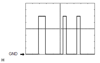
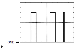
(e) Using an oscilloscope, check waveform 1.
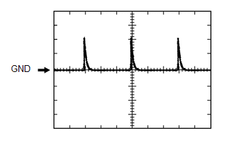 Waveform 1 (Reference)
|
Item |
Content |
|---|---|
|
Terminal No. (Symbol) |
|
|
Tool Setting |
5 V/DIV., 20 ms/DIV. |
|
Condition |
Ignition switch ON, rear washer switch off |
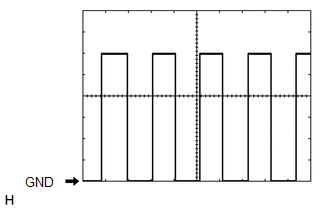
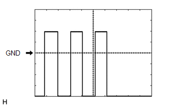
(f) Using an oscilloscope, check waveform 2.
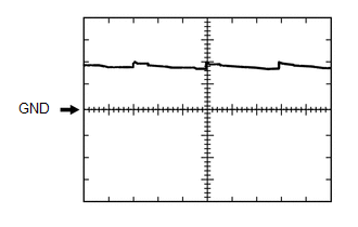 Waveform 2 (Reference)
|
Item |
Content |
|---|---|
|
Terminal No. (Symbol) |
|
|
Tool Setting |
5 V/DIV., 20 ms/DIV. |
|
Condition |
Ignition switch ON, rear washer switch off |
2. CHECK MULTIPLEX NETWORK DOOR ECU (BACK DOOR P/W)
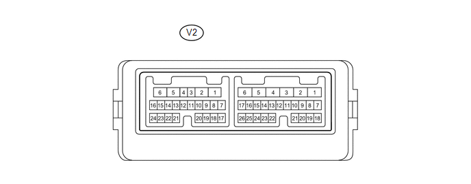
(a) Disconnect the V2 multiplex network door ECU (back door P/W) connector.
(b) Measure the voltage and resistance according to the value(s) in the table below.
HINT:
Measure the values on the wire harness side with the connector disconnected.
|
Terminal No. (Symbol) |
Wiring Color |
Terminal Description |
Condition |
Specified Condition |
|---|---|---|---|---|
|
V2-1 (BDR) - Body ground |
B - Body ground |
Battery power supply |
Always |
11 to 14 V |
|
V2-7 (BECU) - Body ground |
L - Body ground |
Battery power supply |
Always |
11 to 14 V |
|
V2-8 (SIG) - Body ground |
G - Body ground |
Ignition switch power supply |
Ignition switch ON |
11 to 14 V |
|
V2-8 (SIG) - Body ground |
G - Body ground |
Ignition switch power supply |
Ignition switch off |
Below 1 V |
|
V2-6 (GND) - Body ground |
W-B - Body ground |
Ground |
Always |
Below 1 Ω |
If the result is not as specified, there may be a malfunction in the wire harness.
(c) Reconnect the V2 multiplex network door ECU (back door P/W) connector.
(d) Measure the voltage according to the value(s) in the table below.
|
Terminal No. (Symbol) |
Wiring Color |
Terminal Description |
Condition |
Specified Condition |
|---|---|---|---|---|
|
V2-3 (W) - V2-12 (SGND) |
R - G |
Rear wiper reverse position switch input |
Ignition switch ON and rear wiper switch on (rear wiper reverse position switch off) |
Pulse generation (See waveform 1) |
|
V2-3 (W) - V2-12 (SGND) |
R - G |
Rear wiper reverse position switch input |
Ignition switch ON and rear wiper switch on (rear wiper reverse position switch on) |
Pulse generation (See waveform 2) |
|
V2-4 (P) - V2-12 (SGND) |
V - G |
Rear wiper retractable position switch input |
Ignition switch ON and rear wiper switch on (rear wiper retractable position switch off) |
Pulse generation (See waveform 3) |
|
V2-4 (P) - V2-12 (SGND) |
V - G |
Rear wiper retractable position switch input |
Ignition switch ON and rear wiper switch on (rear wiper retractable position switch on) |
Pulse generation (See waveform 4) |
|
V2-2 (WIP+) - V2-6 (GND) |
L - W-B |
Rear wiper motor output |
Ignition switch ON, rear wiper switch INT |
Pulse generation (See waveform 5) |
|
V2-5 (WIP-) - V2-6 (GND) |
P - W-B |
Rear wiper motor output |
Ignition switch ON, rear wiper switch INT |
Pulse generation (See waveform 6) |
|
V2-2 (WIP+) - V2-6 (GND) |
L - W-B |
Rear wiper motor output |
Ignition switch ON, rear wiper switch LO |
Pulse generation (See waveform 7) |
|
V2-5 (WIP-) - V2-6 (GND) |
P - W-B |
Rear wiper motor output |
Ignition switch ON, rear wiper switch LO |
Pulse generation (See waveform 8) |
|
V2-2 (WIP+) - V2-6 (GND) |
L - W-B |
Rear wiper motor output |
Ignition switch ON, rear washer switch on |
Pulse generation (See waveform 9) |
|
V2-5 (WIP-) - V2-6 (GND) |
P - W-B |
Rear wiper motor output |
Ignition switch ON, rear washer switch on |
Pulse generation (See waveform 10) |
|
V2-2 (WIP+) - V2-6 (GND) |
L - W-B |
Rear wiper motor output |
Ignition switch ON, rear wiper switch off |
Pulse generation (See waveform 11) |
|
V2-5 (WIP-) - V2-6 (GND) |
P - W-B |
Rear wiper motor output |
Ignition switch ON, rear wiper switch off |
Pulse generation (See waveform 12) |
If the result is not as specified, the multiplex network door ECU (back door P/W) may have a malfunction.
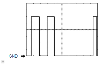
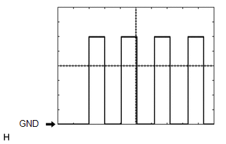
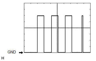
(e) Using an oscilloscope, check waveform 1.
.png) Waveform 1 (Reference)
Waveform 1 (Reference)
|
Item |
Content |
|---|---|
|
Terminal No. (Symbol) |
V2-3 (W) - V2-12 (SGND) |
|
Tool Setting |
5 V/DIV., 10 ms/DIV |
|
Condition |
Ignition switch ON and rear wiper switch on (rear wiper reverse position switch off) |
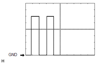
(f) Using an oscilloscope, check waveform 2.
.png) Waveform 2 (Reference)
Waveform 2 (Reference)
|
Item |
Content |
|---|---|
|
Terminal No. (Symbol) |
V2-3 (W) - V2-12 (SGND) |
|
Tool Setting |
5 V/DIV., 10 ms/DIV |
|
Condition |
Ignition switch ON and rear wiper switch on (rear wiper reverse position switch on) |
(g) Using an oscilloscope, check waveform 3.
Waveform 3 (Reference)
|
Item |
Content |
|---|---|
|
Terminal No. (Symbol) |
V2-4 (P) - V2-12 (SGND) |
|
Tool Setting |
2 V/DIV., 2 ms/DIV |
|
Condition |
Ignition switch ON and rear wiper switch on (rear wiper retractable position switch off) |
(h) Using an oscilloscope, check waveform 4.
Waveform 4 (Reference)
|
Item |
Content |
|---|---|
|
Terminal No. (Symbol) |
V2-4 (P) - V2-12 (SGND) |
|
Tool Setting |
2 V/DIV., 2 ms/DIV |
|
Condition |
Ignition switch ON and rear wiper switch on (rear wiper retractable position switch on) |
(i) Using an oscilloscope, check waveform 5.
 Waveform 5 (Reference)
|
Item |
Content |
|---|---|
|
Terminal No. (Symbol) |
V2-2 (WIP+) - V2-6 (GND) |
|
Tool Setting |
2 V/DIV., 2 ms/DIV |
|
Condition |
Ignition switch ON, rear wiper switch INT |
(j) Using an oscilloscope, check waveform 6.
 Waveform 6 (Reference)
|
Item |
Content |
|---|---|
|
Terminal No. (Symbol) |
V2-5 (WIP-) - V2-6 (GND) |
|
Tool Setting |
2 V/DIV., 2 ms/DIV |
|
Condition |
Ignition switch ON, rear wiper switch INT |
(k) Using an oscilloscope, check waveform 7.
 Waveform 7 (Reference)
|
Item |
Content |
|---|---|
|
Terminal No. (Symbol) |
V2-2 (WIP+) - V2-6 (GND) |
|
Tool Setting |
2 V/DIV., 2 ms/DIV |
|
Condition |
Ignition switch ON, rear wiper switch LO |
(l) Using an oscilloscope, check waveform 8.
 Waveform 8 (Reference)
|
Item |
Content |
|---|---|
|
Terminal No. (Symbol) |
V2-5 (WIP-) - V2-6 (GND) |
|
Tool Setting |
2 V/DIV., 2 ms/DIV |
|
Condition |
Ignition switch ON, rear wiper switch LO |
(m) Using an oscilloscope, check waveform 9.
 Waveform 9 (Reference)
|
Item |
Content |
|---|---|
|
Terminal No. (Symbol) |
V2-2 (WIP+) - V2-6 (GND) |
|
Tool Setting |
2 V/DIV., 2 ms/DIV |
|
Condition |
Ignition switch ON, rear washer switch on |
(n) Using an oscilloscope, check waveform 10.
 Waveform 10 (Reference)
|
Item |
Content |
|---|---|
|
Terminal No. (Symbol) |
V2-5 (WIP-) - V2-6 (GND) |
|
Tool Setting |
2 V/DIV., 2 ms/DIV |
|
Condition |
Ignition switch ON, rear washer switch on |
(o) Using an oscilloscope, check waveform 11.
 Waveform 11 (Reference)
|
Item |
Content |
|---|---|
|
Terminal No. (Symbol) |
V2-2 (WIP+) - V2-6 (GND) |
|
Tool Setting |
2 V/DIV., 2 ms/DIV |
|
Condition |
Ignition switch ON, rear wiper switch off |
(p) Using an oscilloscope, check waveform 12.
 Waveform 12 (Reference)
|
Item |
Content |
|---|---|
|
Terminal No. (Symbol) |
V2-5 (WIP-) - V2-6 (GND) |
|
Tool Setting |
2 V/DIV., 2 ms/DIV |
|
Condition |
Ignition switch ON, rear wiper switch off |
 Problem Symptoms Table
PROBLEM SYMPTOMS TABLE
HINT:
Use the table below to help determine the cause of problem symptoms.
If multiple suspected areas are listed, the potential causes of the symptoms
are lis ...
 Data List / Active Test
DATA LIST / ACTIVE TEST
1. READ DATA LIST
HINT:
Using the Techstream to read the Data List allows the values or states of switches,
sensors, actuators and other items to be read without removing ...
Other materials about Toyota 4Runner:
Hydraulic Test
HYDRAULIC TEST
1. PERFORM HYDRAULIC TEST
(a) Measure the line pressure.
CAUTION:
The line pressure test should always be carried out in pairs. One technician
should observe the conditions of the wheels and wheel stoppers from outside the
vehicle while ...
Open in Inside Luggage Compartment Electrical Key Oscillator Circuit (B27A7)
DESCRIPTION
The certification ECU generates a request signal and transmits the signal to
the indoor No. 2 electrical key antenna (inside luggage). The indoor No. 2 electrical
key antenna (inside luggage) detects that the electrical key is inside the vehic ...

0.0099