Toyota 4Runner: Terminals Of Ecu
TERMINALS OF ECU
1. CHECK COMBINATION METER ASSEMBLY
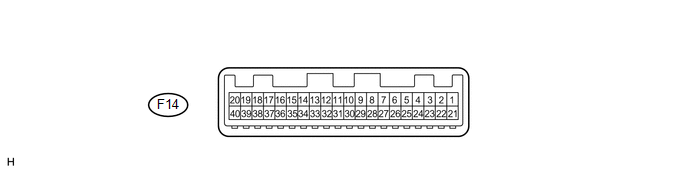
(a) Disconnect the F14 combination meter assembly connector.
(b) Measure the resistance and voltage according to the value(s) in the table below.
|
Terminal No. (Symbol) |
Wiring Color |
Terminal Description |
Condition |
Specified Condition |
|---|---|---|---|---|
|
F14-15 (B) - Body ground |
L - Body ground |
Battery power supply |
Always |
11 to 14 V |
|
F14-17 (IG+) - Body ground |
R - Body ground |
Ignition switch power supply |
Ignition switch off |
Below 1 V |
|
Ignition switch ON |
11 to 14 V |
|||
|
F14-20 (E1) - Body ground |
W-B - Body ground |
Ground |
Always |
Below 1 Ω |
If the result is not as specified, there may be a malfunction on the wire harness side.
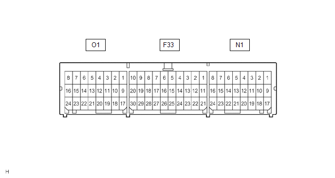
2. CHECK CENTER AIRBAG SENSOR ASSEMBLY
|
Terminal No. |
Symbol |
Description |
|---|---|---|
|
O1-10 |
LBE+ |
Front seat inner belt assembly LH (Seat belt buckle switch LH) |
|
O1-18 |
LBE- |
Front seat inner belt assembly LH (Seat belt buckle switch LH) |
|
N1-16 |
FSR+ |
Occupant detection ECU |
|
N1-24 |
FSR- |
Occupant detection ECU |
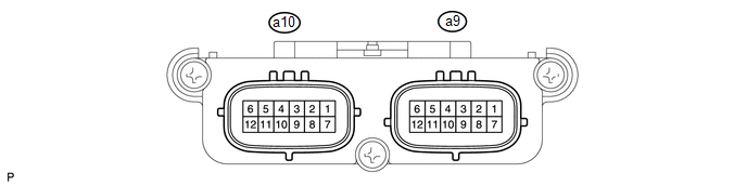
3. CHECK OCCUPANT DETECTION ECU
|
Terminal No. (Symbol) |
Wiring Color |
Terminal Description |
Condition |
Specified Condition |
|---|---|---|---|---|
|
a9-1 (+B) - a9-3 (GND) |
W - W-B |
Battery power supply |
Always |
11 to 14 V |
|
a9-2 (DIA) - a9-3 (GND) |
GR - W-B |
Diagnosis (DLC3) |
Ignition switch ON |
Pulse generation |
|
a9-3 (GND) - Body ground |
W-B - Body ground |
Ground |
Always |
Below 1 V |
|
a9-4 (FSR-) - a9-3 (GND) |
LG - W-B |
Center airbag sensor assembly communication line |
Always |
Below 1 V |
|
a9-5 (BGND) - a9-3 (GND) |
P - W-B |
Front passenger side buckle switch ground line |
Always |
Below 1 V |
|
a9-7 (IG2) - a9-3 (GND) |
B - W-B |
Ignition switch power supply |
Ignition switch ON |
11 to 14 V |
|
a9-8 (FSR+) - a9-4 (FSR-) |
L - LG |
Center airbag sensor assembly communication line |
Ignition switch ON |
Pulse generation |
|
a9-9 (BSW) - a9-5 (BGND) |
G - P |
Front passenger side buckle switch line |
Always |
Pulse generation |
|
a10-1 (SGD1) - a9-3 (GND) |
G - W-B |
Front occupant classification sensor LH ground line |
Always |
Below 1 V |
|
a10-2 (SGD2) - a9-3 (GND) |
LG - W-B |
Front occupant classification sensor RH ground line |
Always |
Below 1 V |
|
a10-3 (SGD3) - a9-3 (GND) |
W - W-B |
Rear occupant classification sensor LH ground line |
Always |
Below 1 V |
|
a10-4 (SGD4) - a9-3 (GND) |
BR - W-B |
Rear occupant classification sensor RH ground line |
Always |
Below 1 V |
|
a10-11 (SVC1) - a10-1 (SGD1) |
R - G |
Front occupant classification sensor LH power supply line |
Ignition switch ON, load applied to front occupant classification sensor LH |
4.9 to 5.1 V |
|
a10-12 (SVC2) - a10-2 (SGD2) |
W - LG |
Front occupant classification sensor RH power supply line |
Ignition switch ON, load applied to front occupant classification sensor RH |
4.9 to 5.1 V |
|
a10-5 (SVC3) - a10-3 (SGD3) |
GR - W |
Rear occupant classification sensor LH power supply line |
Ignition switch ON, load applied to rear occupant classification sensor LH |
4.9 to 5.1 V |
|
a10-6 (SVC4) - a10-4 (SGD4) |
V - BR |
Rear occupant classification sensor RH power supply line |
Ignition switch ON, load applied to rear occupant classification sensor RH |
4.9 to 5.1 V |
|
a10-7 (SIG1) - a10-1 (SGD1) |
P - G |
Front occupant classification sensor LH signal line |
Ignition switch ON, load applied to front occupant classification sensor LH |
0 to 5.1 V |
|
a10-8 (SIG2) - a10-2 (SGD2) |
L - LG |
Front occupant classification sensor RH signal line |
Ignition switch ON, load applied to front occupant classification sensor RH |
0 to 5.1 V |
|
a10-9 (SIG3) - a10-3 (SGD3) |
SB - W |
Rear occupant classification sensor LH signal line |
Ignition switch ON, load applied to rear occupant classification sensor LH |
0 to 5.1 V |
|
a10-10 (SIG4) - a10-4 (SGD4) |
B - BR |
Rear occupant classification sensor RH signal line |
Ignition switch ON, load applied to rear occupant classification sensor RH |
0 to 5.1 V |
If the result is not as specified, the occupant detection ECU may have a malfunction.
 Problem Symptoms Table
PROBLEM SYMPTOMS TABLE
HINT:
Use the table below to help determine the cause of problem symptoms.
If multiple suspected areas are listed, the potential causes of the symptoms
are lis ...
 Data List / Active Test
DATA LIST / ACTIVE TEST
1. READ DATA LIST
HINT:
Using the Techstream to read the Data List allows values or states of switches,
sensors, actuators and other items to be read without removing any ...
Other materials about Toyota 4Runner:
Inspection
INSPECTION
PROCEDURE
1. INSPECT DOOR CONTROL TRANSMITTER MODULE
(a) Inspect the operation of the transmitter.
(1) Remove the battery (lithium battery) from the transmitter (See page
).
(2) Install a new or normal battery (lithium battery).
...
System Description
SYSTEM DESCRIPTION
1. DESCRIPTION
(a) In the Variable Flow Control (VFC) power steering system, the power steering
ECU assembly receives the steering angle signal, steering zero point memory, the
steering speed, vehicle speed signal and engine speed sign ...

0.0065