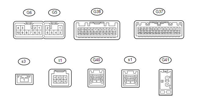
Toyota 4Runner: Terminals Of Ecu
TERMINALS OF ECU
1. NAVIGATION RECEIVER ASSEMBLY (for 9 Speakers)
|
Terminal No. (Symbol) |
Wiring Color |
Terminal Description |
Condition |
Specified Condition |
|---|---|---|---|---|
|
G5-2 (RL+) - G6-7 (GND) |
R - BR |
Voice signal |
Voice guidance sounding |
A waveform synchronized with sounds is output |
|
G5-5 (ILL-) - G6-7 (GND) |
W - BR |
Illumination signal |
Ignition switch off |
Below 1 V |
|
Light control switch in tail or head position |
Pulse generation |
|||
|
G5-6 (RL-) - G6-7 (GND) |
G - BR |
Voice signal |
Voice guidance sounding |
A waveform synchronized with sounds is output |
|
G6-1 (FR+) - G6-7 (GND) |
B - BR |
Sound signal (Right) |
Audio system playing |
A waveform synchronized with sounds is output |
|
G6-2 (FL+) - G6-7 (GND) |
W - BR |
Sound signal (Left) |
Audio system playing |
A waveform synchronized with sounds is output |
|
G6-3 (ACC) - G6-7 (GND) |
GR - BR |
Power source (ACC) |
Ignition switch off |
Below 1 V |
|
Ignition switch ACC |
11 to 14 V |
|||
|
G6-4 (B) - G6-7 (GND) |
SB - BR |
Power source (+B) |
Always |
11 to 14 V |
|
G6-5 (FR-) - G6-7 (GND) |
G - BR |
Sound signal (Right) |
Audio system playing |
A waveform synchronized with sounds is output |
|
G6-6 (FL-) - G6-7 (GND) |
R - BR |
Sound signal (Left) |
Audio system playing |
A waveform synchronized with sounds is output |
|
G6-7 (GND) - Body ground |
BR - Body ground |
Ground |
Always |
Below 1 V |
|
G6-10 (ILL+) - G6-7 (GND) |
G - BR |
Illumination signal |
Light control switch off |
Below 1 V |
|
Light control switch in tail or head position |
11 to 14 V |
|||
|
G37-1 (IG) - G6-7 (GND) |
L - BR |
Power source (IG) |
Ignition switch off |
Below 1 V |
|
Ignition switch ON |
11 to 14 V |
|||
|
G37-2 (REV) - G6-7 (GND) |
R - BR |
Reverse signal |
See "Vehicle Signal Check Mode" in Operation Check (See page
|
- |
|
G37-4 (MACC) - G6-7 (GND) |
R - BR |
Microphone power supply |
Ignition switch off |
Below 1 V |
|
Ignition switch ACC |
4 to 6 V |
|||
|
G37-5 (MIN+) - G6-7 (GND) |
B - BR |
Microphone voice signal |
See "Microphone Check" in Operation Check (See page
|
- |
|
G37-6 (SNS2) - G6-7 (GND) |
G - BR |
Microphone connection detection signal |
Always |
Below 1 V |
|
G37-7 (TX1+) |
B |
AVC-LAN communication signal |
- |
- |
|
G37-8 (TX1-) |
W |
AVC-LAN communication signal |
- |
- |
|
G37-9 (CANH) |
P |
CAN communication signal |
- |
- |
|
G37-10 (CANL) |
W |
CAN communication signal |
- |
- |
|
G37-11 (AGND) - Body ground |
Shield - Body ground |
Shield ground |
Always |
Below 1 V |
|
G37-12 (SG) - G6-7 (GND) |
Shield - BR |
Shield ground |
Always |
Below 1 V |
|
G37-15 (PKB) - G6-7 (GND) |
LG - BR |
Parking brake signal |
See "Vehicle Signal Check Mode" in Operation Check (See page
|
- |
|
G37-17 (SPD) - G6-7 (GND) |
SB - BR |
Vehicle speed signal from combination meter assembly |
See "Vehicle Signal Check Mode" in Operation Check (See page
|
- |
|
G37-18 (SGND) - G6-7 (GND) |
Shield - BR |
Shield ground |
Always |
Below 1 V |
|
G37-19 (MIN-) - Body ground |
W - Body ground |
Microphone voice signal |
See "Microphone Check" in Operation Check (See page
|
- |
|
G37-16 (MUT) - G6-7 (GND) |
L - BR |
Mute signal |
Audio system playing |
Above 3.5 V |
|
Audio system changing modes |
Below 1 V |
|||
|
G37-21 (SW1) - G37-23 (SWG) |
W - L |
Steering pad switch signal |
No switch pushed |
2.97 to 3.56 V |
|
Up switch pushed |
0.27 to 0.35 V |
|||
|
Down switch pushed |
0.86 to 1.03 V |
|||
|
Volume+ switch pushed |
1.51 to 1.79 V |
|||
|
Volume- switch pushed |
2.22 to 2.66 V |
|||
|
G37-22 (SW2) - G37-23 (SWG) |
R - L |
Steering pad switch signal |
No switch pushed |
2.97 to 3.56 V |
|
MODE/HOLD switch pushed |
0.27 to 0.35 V |
|||
|
On hook switch pushed |
0.86 to 1.03 V |
|||
|
Off hook switch pushed |
1.51 to 1.79 V |
|||
|
Voice switch pushed |
2.22 to 2.66 V |
|||
|
G37-23 (SWG) - Body ground |
L - Body ground |
Steering pad switch signal |
Always |
Below 1 V |
|
G37-24 (SW3) - G37-23 (SWG) |
P - L |
Steering pad switch signal |
No switch pushed |
2.97 to 3.56 V |
|
Enter switch pushed |
0.27 to 0.35 V |
|||
|
Back switch pushed |
0.86 to 1.03 V |
|||
|
Right switch pushed |
1.51 to 1.79 V |
|||
|
Left switch pushed |
2.22 to 2.66 V |
|||
|
G37-25 (ADPG) - G6-7 (GND) |
V - BR |
External device connection detection signal |
External device connected |
Below 1 V |
|
External device not connected |
2.1 to 3 V |
|||
|
G37-26 (VAR+) - G37-27 (VA-) |
R - W |
Sound signal (Right) |
External device playing (When stereo jack used) |
A waveform synchronized with sounds is output |
|
G37-27 (VA-) - G6-7 (GND) |
W - BR |
Sound signal ground |
Always |
Below 1 V |
|
G37-28 (VAL+) - G37-27 (VA-) |
B - W |
Sound signal (Left) |
External device playing (When stereo jack used) |
A waveform synchronized with sounds is output |
|
G38-11 (CA+) - G6-7 (GND) |
R - BR |
Television camera power supply |
Ignition switch ON Shift lever in R |
5.5 to 7.05 V |
|
G38-12 (V+) - G6-7 (GND) |
W - BR |
Video signal |
Ignition switch ON Shift lever in R Camera lens not covered, displaying an image |
Pulse generation (Refer to waveform 1) |
|
Ignition switch ON Shift lever in R Camera lens covered, blacking out screen |
Pulse generation (Refer to waveform 2) |
|||
|
G38-23 (CGND) - Body ground |
Shield - Body ground |
Shield ground |
Always |
Below 1 V |
|
G38-24 (V-) - G6-7 (GND) |
B - BR |
Ground |
Always |
Below 1 V |
|
G40-1 (USV1) |
# |
Power source |
- |
- |
|
G40-2 (US1-) |
# |
Data signal |
- |
- |
|
G40-3 (US1+) |
# |
Data signal |
- |
- |
|
G40-4 (UGD1) |
# |
Ground |
- |
- |
|
G41-1 (FMSUB1) |
# |
Radio signal |
- |
- |
|
G41-2 (R+B1) - G6-7 (GND) |
# - BR |
Power source of antenna |
Ignition switch ON Radio switch on and AM or FM selected |
11 to 14 V |
|
G41-3 (AMFM1) |
# |
Radio signal |
- |
- |
|
s1-1 (USV4)*1 |
# |
Power source |
- |
- |
|
s1-2 (US4-)*1 |
# |
Data signal |
- |
- |
|
s1-3 (US4+)*1 |
# |
Data signal |
- |
- |
|
s1-4 (UGD4)*1 |
# |
Ground |
- |
- |
|
s3-1 (LV1)*1 |
# |
LVDS communication signal |
- |
- |
|
t1-3 (ACC2) - G6-7 (GND)*1 |
Y - BR |
Power source (ACC) |
Ignition switch off |
Below 1 V |
|
Ignition switch ACC |
11 to 14V |
|||
|
t1-4 (+B2) - G6-7 (GND)*1 |
R - BR |
Power source (+B) |
Always |
11 to 14V |
|
t1-8 (GND2) - Body ground*1 |
B - Body ground |
Ground |
Always |
Below 1 V |
.gif) )
)- #: There is no color information.
- *1: w/ SDARS System
(a) Reference (Oscilloscope waveform):
.png)
.png)
(1) Waveform 1 (camera lens not covered, displaying an image)
|
Item |
Content |
|---|---|
|
Measurement terminal |
G38-12 (V+) - G6-7 (GND) |
|
Measurement setting |
200 mV/DIV., 50 μsec./DIV. |
|
Condition |
Ignition switch ON, Shift lever in R |
HINT:
The video waveform changes according to the image sent by the television camera assembly.
(2) Waveform 2 (camera lens covered, blacking out the screen)
|
Item |
Content |
|---|---|
|
Measurement terminal |
G38-12 (V+) - G6-7 (GND) |
|
Measurement setting |
200 mV/DIV., 50 μsec./DIV. |
|
Condition |
Ignition switch ON, Shift lever in R |
HINT:
The video waveform changes according to the image sent by the rear television camera assembly.
Text in Illustration|
*a |
Waveform 1 (camera lens not covered, displaying an image) |
|
*b |
Waveform 2 (camera lens covered, blacking out the screen) |
|
*c |
Synchronization Signal |
|
*d |
Video Waveform |
2. NAVIGATION RECEIVER ASSEMBLY (for 8 Speakers)
|
Terminal No. (Symbol) |
Wiring Color |
Terminal Description |
Condition |
Specified Condition |
|---|---|---|---|---|
|
G5-1 (RR+) - G6-7 (GND) |
R - BR |
Sound signal (Right) |
Audio system playing |
A waveform synchronized with sounds is output |
|
G5-2 (RL+) - G6-7 (GND) |
B - BR |
Sound signal (Left) |
Audio system playing |
A waveform synchronized with sounds is output |
|
G5-3 (RR-) - G6-7 (GND) |
W - BR |
Sound signal (Right) |
Audio system playing |
A waveform synchronized with sounds is output |
|
G5-5 (ILL-) - G6-7 (GND) |
W - BR |
Illumination signal |
Ignition switch off |
Below 1 V |
|
Light control switch in tail or head position |
Pulse generation |
|||
|
G5-6 (RL-) - G6-7 (GND) |
Y - BR |
Sound signal (Left) |
Audio system playing |
A waveform synchronized with sounds is output |
|
G6-1 (FR+) - G6-7 (GND) |
P - BR |
Sound signal (Right) |
Audio system playing |
A waveform synchronized with sounds is output |
|
G6-2 (FL+) - G6-7 (GND) |
LG - BR |
Sound signal (Left) |
Audio system playing |
A waveform synchronized with sounds is output |
|
G6-3 (ACC) - G6-7 (GND) |
GR - BR |
Power source (ACC) |
Ignition switch off |
Below 1 V |
|
Ignition switch ACC |
11 to 14 V |
|||
|
G6-4 (B) - G6-7 (GND) |
SB - BR |
Power source (+B) |
Always |
11 to 14 V |
|
G6-5 (FR-) - G6-7 (GND) |
Y - BR |
Sound signal (Right) |
Audio system playing |
A waveform synchronized with sounds is output |
|
G6-6 (FL-) - G6-7 (GND) |
L - BR |
Sound signal (Left) |
Audio system playing |
A waveform synchronized with sounds is output |
|
G6-7 (GND) - Body ground |
BR - Body ground |
Ground |
Always |
Below 1 V |
|
G6-10 (ILL+) - G6-7 (GND) |
G - BR |
Illumination signal |
Light control switch off |
Below 1 V |
|
Light control switch in tail or head position |
11 to 14 V |
|||
|
G37-1 (IG) - G6-7 (GND) |
L - BR |
Power source (IG) |
Ignition switch off |
Below 1 V |
|
Ignition switch ON |
11 to 14 V |
|||
|
G37-2 (REV) - G6-7 (GND) |
R - BR |
Reverse signal |
See "Vehicle Signal Check Mode" in Operation Check (See page
|
- |
|
G37-4 (MACC) - G6-7 (GND) |
R - BR |
Microphone power supply |
Ignition switch off |
Below 1 V |
|
Ignition switch ACC |
4 to 6 V |
|||
|
G37-5 (MIN+) - G6-7 (GND) |
B - BR |
Microphone voice signal |
See "Microphone Check" in Operation Check (See page
|
- |
|
G37-6 (SNS2) - G6-7 (GND) |
G - BR |
Microphone connection detection signal |
Always |
Below 1 V |
|
G37-9 (CANH) |
P |
CAN communication signal |
- |
- |
|
G37-10 (CANL) |
W |
CAN communication signal |
- |
- |
|
G37-11 (AGND) - Body ground |
Shield - Body ground |
Shield ground |
Always |
Below 1 V |
|
G37-12 (SG) - G6-7 (GND) |
Shield - BR |
Shield ground |
Always |
Below 1 V |
|
G37-13 (VV+) - G6-7 (GND) |
B - BR |
Video signal |
External device playing (When stereo jack used) |
A waveform synchronized with sounds is output |
|
G37-14 (VV-) - G6-7 (GND) |
W - BR |
Video signal ground |
Always |
Below 1 V |
|
G37-15 (PKB) - G6-7 (GND) |
LG - BR |
Parking brake signal |
See "Vehicle Signal Check Mode" in Operation Check (See page
|
- |
|
G37-17 (SPD) - G6-7 (GND) |
SB - BR |
Vehicle speed signal from combination meter assembly |
See "Vehicle Signal Check Mode" in Operation Check (See page
|
- |
|
G37-18 (SGND) - G6-7 (GND) |
Shield - BR |
Shield ground |
Always |
Below 1 V |
|
G37-19 (MIN-) - Body ground |
W - Body ground |
Microphone voice signal |
See "Microphone Check" in Operation Check (See page
|
- |
|
G37-21 (SW1) - G37-23 (SWG) |
W - L |
Steering pad switch signal |
No switch pushed |
2.97 to 3.56 V |
|
Up switch pushed |
0.27 to 0.35 V |
|||
|
Down switch pushed |
0.86 to 1.03 V |
|||
|
Volume+ switch pushed |
1.51 to 1.79 V |
|||
|
Volume- switch pushed |
2.22 to 2.66 V |
|||
|
G37-22 (SW2) - G37-23 (SWG) |
R - L |
Steering pad switch signal |
No switch pushed |
2.97 to 3.56 V |
|
MODE/HOLD switch pushed |
0.27 to 0.35 V |
|||
|
On hook switch pushed |
0.86 to 1.03 V |
|||
|
Off hook switch pushed |
1.51 to 1.79 V |
|||
|
Voice switch pushed |
2.22 to 2.66 V |
|||
|
G37-23 (SWG) - Body ground |
L - Body ground |
Steering pad switch signal |
Always |
Below 1 V |
|
G37-24 (SW3) - G37-23 (SWG) |
P - L |
Steering pad switch signal |
No switch pushed |
2.97 to 3.56 V |
|
Enter switch pushed |
0.27 to 0.35 V |
|||
|
Back switch pushed |
0.86 to 1.03 V |
|||
|
Right switch pushed |
1.51 to 1.79 V |
|||
|
Left switch pushed |
2.22 to 2.66 V |
|||
|
G37-25 (ADPG) - G6-7 (GND) |
V - BR |
External device connection detection signal |
External device connected |
Below 1 V |
|
External device not connected |
2.1 to 3 V |
|||
|
G37-26 (VAR+) - G37-27 (VA-) |
R - W |
Sound signal (Right) |
External device playing (When stereo jack used) |
A waveform synchronized with sounds is output |
|
G37-27 (VA-) - G6-7 (GND) |
W - BR |
Sound signal ground |
Always |
Below 1 V |
|
G37-28 (VAL+) - G37-27 (VA-) |
B - W |
Sound signal (Left) |
External device playing (When stereo jack used) |
A waveform synchronized with sounds is output |
|
G38-11 (CA+) - G6-7 (GND) |
R - BR |
Television camera power supply |
Ignition switch ON Shift lever in R |
5.5 to 7.05 V |
|
G38-12 (V+) - G6-7 (GND) |
W - BR |
Video signal |
Ignition switch ON Shift lever in R Camera lens not covered, displaying an image |
Pulse generation (Refer to waveform 1) |
|
Ignition switch ON Shift lever in R Camera lens covered, blacking out screen |
Pulse generation (Refer to waveform 2) |
|||
|
G38-23 (CGND) - Body ground |
Shield - Body ground |
Shield ground |
Always |
Below 1 V |
|
G38-24 (V-) - G6-7 (GND) |
B - BR |
Ground |
Always |
Below 1 V |
|
G40-1 (USV1) |
# |
Power source |
- |
- |
|
G40-2 (US1-) |
# |
Data signal |
- |
- |
|
G40-3 (US1+) |
# |
Data signal |
- |
- |
|
G40-4 (UGD1) |
# |
Ground |
- |
- |
|
G41-1 (FMSUB1) |
# |
Radio signal |
- |
- |
|
G41-2 (R+B1) - G6-7 (GND) |
# - BR |
Power source of antenna |
Ignition switch ON Radio switch on and AM or FM selected |
11 to 14 V |
|
G41-3 (AMFM1) |
# |
Radio signal |
- |
- |
|
s1-1 (USV4)*1 |
# |
Power source |
- |
- |
|
s1-2 (US4-)*1 |
# |
Data signal |
- |
- |
|
s1-3 (US4+)*1 |
# |
Data signal |
- |
- |
|
s1-4 (UGD4)*1 |
# |
Ground |
- |
- |
|
s3-1 (LV1)*1 |
# |
LVDS communication signal |
- |
- |
|
t1-3 (ACC2) - G6-7 (GND)*1 |
Y - BR |
Power source (ACC) |
Ignition switch off |
Below 1 V |
|
Ignition switch ACC |
11 to 14V |
|||
|
t1-4 (+B2) - G6-7 (GND)*1 |
R - BR |
Power source (+B) |
Always |
11 to 14V |
|
t1-8 (GND2) - Body ground*1 |
B - Body ground |
Ground |
Always |
Below 1 V |
- #: There is no color information.
- *1: w/ SDARS System
(a) Reference (Oscilloscope waveform):
(1) Waveform 1 (camera lens not covered, displaying an image)
|
Item |
Content |
|---|---|
|
Measurement terminal |
G38-12 (V+) - G6-7 (GND) |
|
Measurement setting |
200 mV/DIV., 50 μsec./DIV. |
|
Condition |
Ignition switch ON, Shift lever in R |
HINT:
The video waveform changes according to the image sent by the television camera assembly.
(2) Waveform 2 (camera lens covered, blacking out the screen)
|
Item |
Content |
|---|---|
|
Measurement terminal |
G38-12 (V+) - G6-7 (GND) |
|
Measurement setting |
200 mV/DIV., 50 μsec./DIV. |
|
Condition |
Ignition switch ON, Shift lever in R |
HINT:
The video waveform changes according to the image sent by the rear television camera assembly.
Text in Illustration|
*a |
Waveform 1 (camera lens not covered, displaying an image) |
|
*b |
Waveform 2 (camera lens covered, blacking out the screen) |
|
*c |
Synchronization Signal |
|
*d |
Video Waveform |
3. STEREO COMPONENT TUNER ASSEMBLY (w/ SDARS System)
.png)
|
Terminal No. (Symbol) |
Wiring Color |
Terminal Description |
Condition |
Specified Condition |
|---|---|---|---|---|
|
t2-3 (ACC2) - t2-8 (GND2) |
Y - B |
Power source (ACC) |
Ignition switch off |
Below 1 V |
|
Ignition switch ACC |
11 to 14 V |
|||
|
t2-4 (+B2) - t2-8 (GND2) |
R - B |
Power source (+B) |
Always |
11 to 14 V |
|
t2-8 (GND2) - Body ground |
B - Body ground |
Ground |
Always |
Below 1 V |
|
s2-1 (USV4) |
# |
Power source |
- |
- |
|
s2-2 (USV4-) |
# |
Data signal |
- |
- |
|
s2-3 (USV4+) |
# |
Data signal |
- |
- |
|
s2-4 (UGD4) |
# |
Ground |
- |
- |
|
s2-5 (USG4) |
# |
Shield ground |
- |
- |
|
s4-1 (LV1) |
# |
LVDS communication signal |
- |
- |
|
G42-1 (SDARS1) |
# |
Satellite radio signal |
- |
- |
- #: There is no wire color information
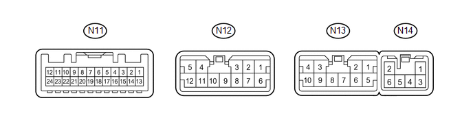
4. STEREO COMPONENT AMPLIFIER ASSEMBLY (for 9 Speakers)
|
Terminal No. (Symbol) |
Wiring Color |
Terminal Description |
Condition |
Specified Condition |
|---|---|---|---|---|
|
N14-1 (+B) - N14-2 (GND) |
SB - BR |
Battery |
Always |
11 to 14 V |
|
N14-2 (GND) - Body ground |
BR - Body ground |
Ground |
Always |
Below 1 V |
|
N14-3 (+B2) - N14-2 (GND) |
SB - BR |
Battery |
Always |
11 to 14 V |
|
N14-6 (GND2) - Body ground |
BR - Body ground |
Ground |
Always |
Below 1 V |
|
N11-1 (MUTE) - N14-2 (GND) |
L - BR |
Mute signal |
Audio system playing |
Higher than 3.5 V |
|
Audio system source changed |
Below 1 V |
|||
|
N11-2 (L-) - N14-2 (GND) |
R - BR |
Sound signal (Left) |
Audio system playing |
Waveform synchronized with sounds is output |
|
N11-3 (L+) - N14-2 (GND) |
W - BR |
Sound signal (Left) |
Audio system playing |
Waveform synchronized with sounds is output |
|
N11-4 (R-) - N14-2 (GND) |
G - BR |
Sound signal (Right) |
Audio system playing |
Waveform synchronized with sounds is output |
|
N11-5 (R+) - N14-2 (GND) |
B - BR |
Sound signal (Right) |
Audio system playing |
Waveform synchronized with sounds is output |
|
N11-6 (SLD) - N14-2 (GND) |
Shielded - BR |
Shield ground |
Always |
Below 1 V |
|
N11-7 (TX-) |
W |
AVC-LAN communication signal |
- |
- |
|
N11-8 (TX+) |
B |
AVC-LAN communication signal |
- |
- |
|
N11-11 (SPD) - N14-2 (GND) |
SB - BR |
Speed signal from combination meter |
Ignition switch ON, drive wheels turned slowly |
Pulse generation |
|
N11-12 (ACC) - N14-2 (GND) |
GR - BR |
Ignition switch ACC |
Ignition switch off |
Below 1 V |
|
Ignition switch ACC |
11 to 14 V |
|||
|
N11-14 (II1-) - N14-2 (GND) |
G - BR |
Voice signal |
"Bluetooth" handsfree voice signal playing |
Waveform synchronized with sounds is output |
|
N11-15 (II1+) - N14-2 (GND) |
R - BR |
Voice signal |
"Bluetooth" handsfree voice signal playing |
Waveform synchronized with sounds is output |
|
N11-18 (SLD1) - N14-2 (GND) |
Shielded - BR |
Shield ground |
Always |
Below 1 V |
|
N11-24 (TMUT) - N14-2 (GND)*1 |
L - BR |
Mute signal |
Audio system playing |
Higher than 3.5 V |
|
Emergency call mode |
Below 1 V |
|||
|
N12-1 (TWL+) - N14-2 (GND) |
LG - BR |
Sound signal (Left) |
Audio system playing |
Waveform synchronized with sounds is output |
|
N12-2 (TWR+) - N14-2 (GND) |
P - BR |
Sound signal (Right) |
Audio system playing |
Waveform synchronized with sounds is output |
|
N12-3 (FL+) - N14-2 (GND) |
P - BR |
Sound signal (Left) |
Audio system playing |
Waveform synchronized with sounds is output |
|
N12-4 (RL+) - N14-2 (GND) |
B - BR |
Sound signal (Left) |
Audio system playing |
Waveform synchronized with sounds is output |
|
N12-5 (RR+) - N14-2 (GND) |
R - BR |
Sound signal (Right) |
Audio system playing |
Waveform synchronized with sounds is output |
|
N12-6 (TWL-) - N14-2 (GND) |
L - BR |
Sound signal (Left) |
Audio system playing |
Waveform synchronized with sounds is output |
|
N12-7 (TWR-) - N14-2 (GND) |
Y - BR |
Sound signal (Right) |
Audio system playing |
Waveform synchronized with sounds is output |
|
N12-8 (FL-) - N14-2 (GND) |
V - BR |
Sound signal (Left) |
Audio system playing |
Waveform synchronized with sounds is output |
|
N12-9 (FR-) - N14-2 (GND) |
L - BR |
Sound signal (Right) |
Audio system playing |
Waveform synchronized with sounds is output |
|
N12-10 (FR+) - N14-2 (GND) |
LG - BR |
Sound signal (Right) |
Audio system playing |
Waveform synchronized with sounds is output |
|
N12-11 (RL-) - N14-2 (GND) |
Y - BR |
Sound signal (Left) |
Audio system playing |
Waveform synchronized with sounds is output |
|
N12-12 (RR-) - N14-2 (GND) |
W - BR |
Sound signal (Right) |
Audio system playing |
Waveform synchronized with sounds is output |
|
N13-1 (WF2+) - N14-2 (GND) |
L - BR |
Sound signal (Woofer box) |
Audio system playing |
Waveform synchronized with sounds is output |
|
N13-2 (WF1+) - N14-2 (GND) |
B - BR |
Sound signal (Woofer box) |
Audio system playing |
Waveform synchronized with sounds is output |
|
N13-3 (R-L+) - N14-2 (GND) |
P - BR |
Sound signal (Left) |
Audio system playing |
Waveform synchronized with sounds is output |
|
N13-4 (R-R+) - N14-2 (GND) |
B - BR |
Sound signal (Right) |
Audio system playing |
Waveform synchronized with sounds is output |
|
N13-5 (WF2-) - N14-2 (GND) |
P - BR |
Sound signal (Woofer box) |
Audio system playing |
Waveform synchronized with sounds is output |
|
N13-6 (WF1-) - N14-2 (GND) |
W - BR |
Sound signal (Woofer box) |
Audio system playing |
Waveform synchronized with sounds is output |
|
N13-9 (R-L-) - N14-2 (GND) |
Y - BR |
Sound signal (Left) |
Audio system playing |
Waveform synchronized with sounds is output |
|
N13-10 (R-R-) - N14-2 (GND) |
W - BR |
Sound signal (Right) |
Audio system playing |
Waveform synchronized with sounds is output |
- *1: w/ Manual (SOS) Switch
 Problem Symptoms Table
PROBLEM SYMPTOMS TABLE
NOTICE:
After replacing the navigation receiver assembly of vehicles subscribed to pay-type
satellite radio broadcasts, registration of the XM radio ID is necessary.
HIN ...
 Dtc Check / Clear
DTC CHECK / CLEAR
1. CHECK DTC (CHECK USING TECHSTREAM)
(a) Connect the Techstream to the DLC3.
(b) Turn the ignition switch to ON.
(c) Turn the Techstream on.
(d) Enter the following menus: Body ...
Other materials about Toyota 4Runner:
ACC Signal Circuit
DESCRIPTION
This circuit detects the ignition switch ACC or off condition, and sends it to
the main body ECU.
WIRING DIAGRAM
CAUTION / NOTICE / HINT
NOTICE:
Inspect the fuses for circuits related to this system before performing the following
inspec ...
Center Airbag Sensor Assembly Communication Circuit Malfunction (B1790)
DESCRIPTION
The center airbag sensor communication circuit consists of the occupant classification
ECU and center airbag sensor.
DTC B1790 is stored when a malfunction is detected in the center airbag sensor
communication circuit.
DTC Code
...

0.0319