Toyota 4Runner: Tire Pressure Warning Ecu
Components
COMPONENTS
ILLUSTRATION
Installation
INSTALLATION
PROCEDURE
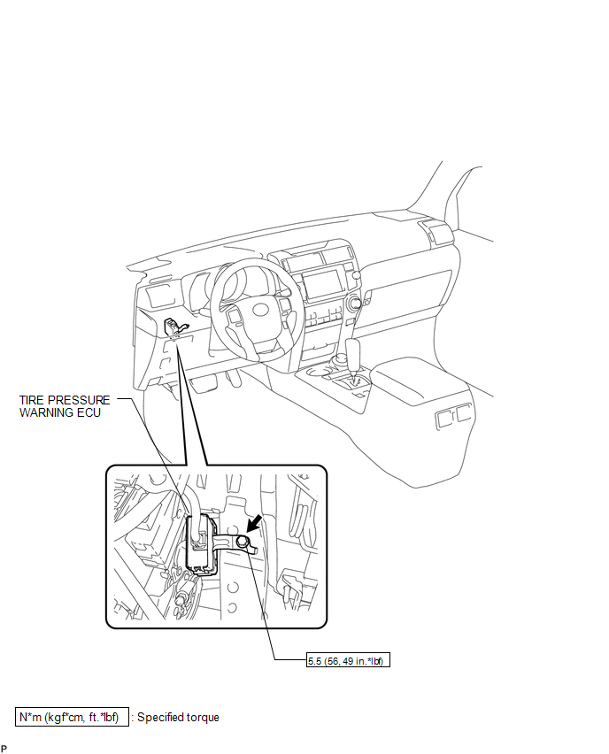
1. INSTALL TIRE PRESSURE WARNING ECU
(a) Install the tire pressure warning ECU with the bolt.
Torque:
5.5 N·m {56 kgf·cm, 49 in·lbf}
(b) Connect the connector.
2. INSTALL LOWER NO. 1 INSTRUMENT PANEL AIRBAG ASSEMBLY
(a) Install the lower No. 1 instrument panel airbag assembly (See page
.gif) ).
).
3. PERFORM REGISTRATION OF TRANSMITTER ID
(a) Perform registration of the transmitter ID (See page
).
Removal
REMOVAL
PROCEDURE
1. REMOVE LOWER NO. 1 INSTRUMENT PANEL AIRBAG ASSEMBLY
(a) Remove the lower No. 1 instrument panel airbag assembly (See page
.gif) ).
).
2. REMOVE TIRE PRESSURE WARNING ECU
|
(a) Disconnect the connector. |
|
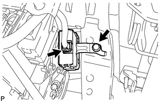
(b) Remove the bolt and tire pressure warning ECU.

 Tire Pressure Warning Receiver(w/ Antenna)
Components
COMPONENTS
ILLUSTRATION
Removal
REMOVAL
PROCEDURE
1. REMOVE ROOF HEADLINING ASSEMBLY
(a) Remove the roof headlining assembly (See page
).
2. REMOVE TIRE PRESSURE WARNING ANT ...
Other materials about Toyota 4Runner:
Lost Communication with Front Airbag Sensor RH (B1612/83,B1613/83)
DESCRIPTION
The front airbag sensor RH circuit consists of the center airbag sensor and front
airbag sensor RH.
The front airbag sensor RH detects impacts to the vehicle and sends signals to
the center airbag sensor to determine if the airbag should be d ...
Cellular Phone Registration Failure
PROCEDURE
1.
CHECK USAGE CONDITION
(a) Check that the vehicle and cellular phone meet the following conditions:
NOTICE:
If changing cellular phone settings, updating software, etc. is necessary, make
sure to obtain the per ...

0.0213