Toyota 4Runner: Tire Pressure Warning Receiver(w/ Antenna)
Components
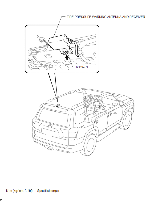
COMPONENTS
ILLUSTRATION
Removal
REMOVAL
PROCEDURE
1. REMOVE ROOF HEADLINING ASSEMBLY
(a) Remove the roof headlining assembly (See page
.gif) ).
).
2. REMOVE TIRE PRESSURE WARNING ANTENNA AND RECEIVER
|
(a) Disconnect the connector. |
|
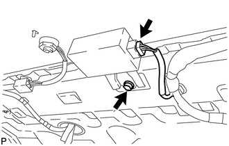
(b) Remove the bolt and receiver assembly.
Installation
INSTALLATION
PROCEDURE
1. INSTALL TIRE PRESSURE WARNING ANTENNA AND RECEIVER
(a) Install the receiver assembly with the bolt.
Torque:
10 N·m {102 kgf·cm, 7 ft·lbf}
(b) Connect the connector.
2. INSTALL ROOF HEADLINING ASSEMBLY
(a) Install the roof headlining assembly (See page
.gif) ).
).
3. PERFORM REGISTRATION OF TRANSMITTER ID
(a) Perform registration of the transmitter ID (See page
).
 Tire Pressure Warning Ecu
Components
COMPONENTS
ILLUSTRATION
Installation
INSTALLATION
PROCEDURE
1. INSTALL TIRE PRESSURE WARNING ECU
(a) Install the tire pressure warning ECU with the bolt.
Torque:
5.5 N·m {5 ...

Other materials about Toyota 4Runner:
Auto Down Operation does not Fully Open Power Window (Catch Protection Function
is Activated)
DESCRIPTION
If any door glass or a power window regulator motor assembly does not operate
smoothly, the catch protection function may be triggered automatically, resulting
in the auto down operation being unable to fully open the power window.
CAUTION / ...
Data List / Active Test
DATA LIST / ACTIVE TEST
1. READ DATA LIST
HINT:
Using the Techstream to read the Data List allows the values or states of switches,
sensors, actuators and other items to be read without removing any parts. This non-intrusive
inspection can be very usefu ...

0.0256