Toyota 4Runner: Vehicle Speed or Engine Speed Signal Malfunction (C2173/73)
DESCRIPTION
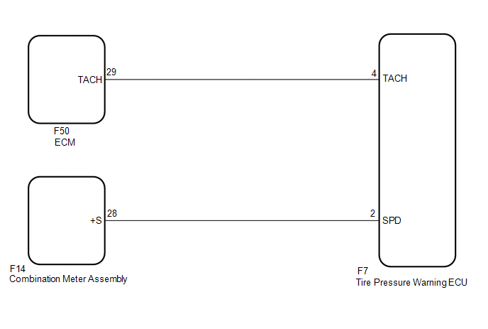
The tire pressure warning ECU receives a vehicle speed signal from the combination meter and an engine speed signal from the ECM. The tire pressure warning ECU uses these signals to store DTCs C2121/21 to C2124/24 or C2125/25*.
- *: w/ Spare Tire Pressure Warning Valve and Transmitter
|
DTC Code |
Detection Condition |
Trouble Area |
|---|---|---|
|
C2173/73 |
Either condition is met for a total of 15 minutes: (a) No engine speed signal while the vehicle speed is 8 km/h (5 mph) or more. (b) No vehicle speed signal while the engine speed is a specified value. |
|
HINT:
This DTC is stored at the same time DTCs C2121/21 to C2124/24 or C2125/25* are stored.
- *: w/ Spare Tire Pressure Warning Valve and Transmitter
WIRING DIAGRAM
CAUTION / NOTICE / HINT
NOTICE:
- When replacing the tire pressure warning ECU, read the IDs stored in the old ECU using the Techstream and write them down before removal.
- It is necessary to perform registration of the transmitter IDs into
the tire pressure warning ECU after the ECU and/or the tire pressure warning
valve and transmitter has been replaced (See page
.gif) ).
).
PROCEDURE
|
1. |
PERFORM SIGNAL CHECK (VEHICLE SPEED SIGNAL AND ENGINE SPEED SIGNAL) |
(a) Enter signal check mode in the Test Mode Procedure (See page
).
(b) Drive the vehicle at 20 km/h (12 mph) or more for 10 seconds to clear DTCs C2191/91 and C2194/94.
(c) Check the test mode DTCs.
Result|
Result |
Proceed to |
|---|---|
|
DTCs C2191/91 and C2194/94 are cleared |
A |
|
DTC C2191/91 is output |
B |
|
DTC C2194/94 is output |
C |
HINT:
DTCs C2181/81 to C2184/84 or C2185/85* (Transmitter ID not Received) are output at this time, but they are not related to this check.
- *: w/ Spare Tire Pressure Warning Valve and Transmitter
| A | .gif) |
USE SIMULATION METHOD TO CHECK |
| B | |
GO TO DTC C2191/91 |
| C | |
GO TO DTC C2194/94 |
 Receiver Error (C2176/76)
DESCRIPTION
The signals are transmitted to the tire pressure warning antenna and receiver
on the body as radio waves and then sent to the tire pressure warning ECU.
DTC Code
...
 Transmitter ID not Received in Main Mode (C2126/26)
DESCRIPTION
After all IDs are registered, DTC C2126/26 is stored in the tire pressure warning
ECU and the tire pressure warning light blinks for 1 minute and then comes on.
When the tire pressure ...
Other materials about Toyota 4Runner:
Acn Call End
ACN CALL END
1. ACN CALL END
This function terminates the ACN (Automatic Collision Notification) to the telematics
provider. After a collision in which the DCM receives a "Collision Detection Signal",
the vehicle will send the emergency call no ...
Removal
REMOVAL
PROCEDURE
1. REMOVE FRONT BUMPER COVER (w/o Intuitive Parking Assist System)
(See page )
2. REMOVE FRONT BUMPER COVER (w/ Intuitive Parking Assist System)
(See page )
3. REMOVE HIGH PITCHED HORN ASSEMBLY
4. REMOVE RADIATOR GRILLE BRACKET
...

0.0097