Toyota 4Runner: Receiver Error (C2176/76)
DESCRIPTION
The signals are transmitted to the tire pressure warning antenna and receiver on the body as radio waves and then sent to the tire pressure warning ECU.
|
DTC Code |
DTC Detection Condition |
Trouble Area |
|---|---|---|
|
C2176/76 |
A malfunction in the tire pressure warning ECU internal circuit. |
|
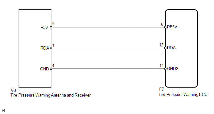
WIRING DIAGRAM
CAUTION / NOTICE / HINT
NOTICE:
- When replacing the tire pressure warning ECU, read the IDs stored in the old ECU using the Techstream and write them down before removal.
- It is necessary to perform registration of the transmitter IDs into
the tire pressure warning ECU after the ECU and/or the tire pressure warning
valve and transmitter has been replaced (See page
.gif) ).
).
PROCEDURE
|
1. |
CHECK HARNESS AND CONNECTOR (ECU - RECEIVER) |
(a) Disconnect the F7 ECU connector.
(b) Disconnect the V3 receiver connector.
(c) Measure the resistance according to the value(s) in the table below.
Standard Resistance:
|
Tester Connection |
Condition |
Specified Condition |
|---|---|---|
|
F7-12 (RDA) - V3-1 (RDA) |
Always |
Below 1 Ω |
|
F7-11 (GND2) - V3-4 (GND) |
Always |
Below 1 Ω |
|
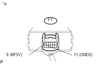
F7-6 (RF5V) - V3-5 (+5V) |
Always |
Below 1 Ω |
|
F7-12 (RDA) or V3-1 (RDA) - Body ground |
Always |
10 kΩ or higher |
|
F7-11 (GND2) or V3-4 (GND) - Body ground |
Always |
10 kΩ or higher |
|
F7-6 (RF5V) or V3-5 (+5V) - Body ground |
Always |
10 kΩ or higher |
| NG | .gif) |
REPAIR OR REPLACE HARNESS OR CONNECTOR |
|
.gif)
|
2. |
CHECK TIRE PRESSURE WARNING ECU |
|
(a) Measure the voltage according to the value(s) in the table below. Standard Voltage:
|
|
| OK | |
REPLACE TIRE PRESSURE WARNING ANTENNA AND RECEIVER |
| NG | |
REPLACE TIRE PRESSURE WARNING ECU |
 Diagnostic Trouble Code Chart
DIAGNOSTIC TROUBLE CODE CHART
Tire pressure warning system
DTC Code
Detection Item
See page
C2111/11
Transmitter ID1 Operation Stop
...
 Vehicle Speed or Engine Speed Signal Malfunction (C2173/73)
DESCRIPTION
The tire pressure warning ECU receives a vehicle speed signal from the combination
meter and an engine speed signal from the ECM. The tire pressure warning ECU uses
these signals to s ...
Other materials about Toyota 4Runner:
Sound Quality is Bad Only when CD is Played (Volume is Too Low)
PROCEDURE
1.
REPLACE CD AND RECHECK
(a) Replace the CD with a known good one and check that the malfunction disappears.
OK:
Malfunction disappears.
OK
END
NG
REPLACE RADIO AN ...
Reassembly
REASSEMBLY
CAUTION / NOTICE / HINT
HINT:
Use the same procedure for both the RH and LH sides.
The procedure listed below is for the LH side.
PROCEDURE
1. INSTALL NO. 3 OUTSIDE MOULDING RETAINER
2. INSTALL REAR DOOR OUTSIDE MOULDING L ...

0.0264