Toyota 4Runner: System Diagram
SYSTEM DIAGRAM
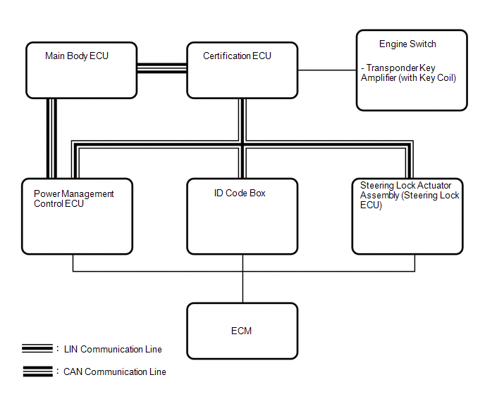 Input and Output Signal of Each ECU
|
Transmitting ECU (Transmitter) |
Receiving ECU (Receiver) |
Signal |
Communication Method |
|---|---|---|---|
|
Power management control ECU |
Steering lock actuator assembly (steering lock ECU) |
Power supply status (to steering lock motor) |
LIN |
|
Steering lock actuator assembly (steering lock ECU) |
|
Sleep available status |
LIN |
|
Steering lock actuator assembly (steering lock ECU) |
|
Lock/unlock sensor status |
LIN |
|
Steering lock actuator assembly (steering lock ECU) |
|
Steering lock status |
LIN |
|
Steering lock actuator assembly (steering lock ECU) |
|
Motor control status |
LIN |
|
Steering lock actuator assembly (steering lock ECU) |
|
Diagnostic response status |
LIN |
|
Steering lock actuator assembly (steering lock ECU) |
|
Lock/unlock sensor malfunction |
LIN |
|
Steering lock actuator assembly (steering lock ECU) |
|
Power supply malfunction (to steering lock motor) |
LIN |
|
Steering lock actuator assembly (steering lock ECU) |
|
Motor driver malfunction |
LIN |
|
Steering lock actuator assembly (steering lock ECU) |
|
Lock bar (stuck) status |
LIN |
|
Steering lock actuator assembly (steering lock ECU) |
|
Push start status |
LIN |
|
Steering lock actuator assembly (steering lock ECU) |
|
Lock/unlock relay drive status |
LIN |
|
Steering lock actuator assembly (steering lock ECU) |
|
Engine start control status |
LIN |
|
Certification ECU |
Steering lock actuator assembly (steering lock ECU) |
Lock/unlock request |
LIN |
|
Main body ECU |
|
Driver side door courtesy switch signal |
CAN |
 System Description
SYSTEM DESCRIPTION
1. DESCRIPTION
(a) The steering lock system locks or unlocks the steering by activating the
steering lock bar with a motor. The steering lock ECU activates the motor based
on ...
 How To Proceed With Troubleshooting
CAUTION / NOTICE / HINT
HINT:
Use the following procedures to troubleshoot the steering lock system.
*: Use the Techstream.
PROCEDURE
1.
VEHICLE BROUGHT ...
Other materials about Toyota 4Runner:
Center Differential Lock Position Switch (C1282)
DESCRIPTION
DTC C1282 is stored only in test mode.
DTC Code
DTC Detection Condition
Trouble Area
C1282
Stored during test mode.
Harness or connector
Transfer system
...
Dcm Activation
DCM ACTIVATION
1. DCM ACTIVATION
This function should be used to activate the DCM (Telematics Transceiver) after
a new DCM (Telematics Transceiver) has been installed. During the DCM (Telematics
Transceiver) activation process, the Techstream automatical ...

0.0096