Toyota 4Runner: VFC Solenoid Circuit (C15F0)
DESCRIPTION
This circuit supplies electric power to the power steering solenoid valve.
The power steering ECU assembly controls the output current to the power steering solenoid valve in accordance with the steering angle signal, steering zero point memory, vehicle speed signal and engine speed signal, adjusting the amount of power steering assist.
|
DTC Code |
DTC Detection Condition |
Trouble area |
|---|---|---|
|
C15F0 |
A short or open in the solenoid valve circuit. |
|
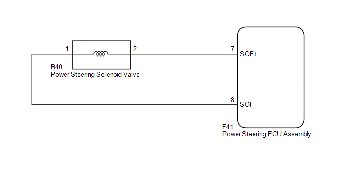
WIRING DIAGRAM
PROCEDURE
|
1. |
READ VALUE USING TECHSTREAM (SOLENOID CURRENT) |
(a) Turn the ignition switch off.
(b) Connect the Techstream to the DLC3.
(c) Turn the ignition switch to ON.
(d) Turn the Techstream on.
(e) Enter the following menus: Chassis / PPS / Data List.
PPS|
Tester Display |
Measurement Item/Range |
Normal Condition |
Diagnostic Note |
|---|---|---|---|
|
Solenoid Current |
Solenoid Current/ Min.: 0 mA Max.: 1000 mA |
200 to 950 mA |
The engine is running and the steering wheel is being turned. |
OK:
The normal condition value is displayed on the Techstream.
| OK | .gif) |
REPLACE POWER STEERING ECU ASSEMBLY |
|
.gif)
|
2. |
CHECK HARNESS AND CONNECTOR (POWER STEERING ECU ASSEMBLY - POWER STEERING SOLENOID VALVE) |
(a) Disconnect the F41 power steering ECU assembly connector.
(b) Disconnect the B40 power steering solenoid valve connector.
(c) Measure the resistance according to the value(s) in the table below.
Standard Resistance:
|
Tester Connection |
Condition |
Specified Condition |
|---|---|---|
|
F41-7 (SOF+) - B40-2 |
Always |
Below 1 Ω |
|
F41-8 (SOF-) - B40-1 |
||
|
F41-7 (SOF+) or B40-2 - Body ground |
Always |
10 kΩ or higher |
|
F41-8 (SOF-) or B40-1 - Body ground |
| NG | |
REPAIR OR REPLACE HARNESS OR CONNECTOR |
|
|
3. |
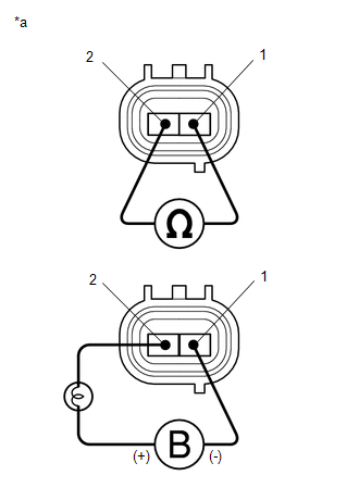
INSPECT POWER STEERING SOLENOID VALVE ASSEMBLY |
(a) Disconnect the B40 power steering solenoid valve connector.
(b) Measure the resistance according to the value(s) in the table below.
Standard Resistance:
|
Tester Connection |
Condition |
Specified Condition |
|---|---|---|
|
1 - 2 |
20°C (68°F) |
6.7 to 7.3 Ω |
(c) Connect the positive (+) lead of the battery with a 21 W bulb to terminal 2 and the negative (-) lead to terminal 1 of the solenoid valve connector. Then check that the valve moves and makes an operating noise.
OK:
Valve moves and makes an operating noise.
Text in Illustration|
*a |
Component without harness connected (Power Steering Solenoid Valve) |
| OK | |
REPLACE POWER STEERING ECU ASSEMBLY |
| NG | |
REPLACE VANE PUMP ASSEMBLY |
 Diagnostic Trouble Code Chart
DIAGNOSTIC TROUBLE CODE CHART
HINT:
If a trouble code is output during the DTC check, inspect the trouble areas listed
for that code. For details of the code, refer to the "See page" bel ...
 Steering Angle Sensor Circuit (C15F1)
DESCRIPTION
The power steering ECU assembly receives steering angle signals from the steering
angle sensor via CAN communication. The power steering ECU assembly provides appropriate
assisting fo ...
Other materials about Toyota 4Runner:
Telematics Transceiver Malfunction (B15A8)
DESCRIPTION
This DTC is stored when an error in EEPROM or PLL IC is detected during the DCM
(Telematics Transceiver) self-check. The EEPROM (Electrically Erasable Programmable
Read-Only Memory) stores the various data to operate Safety Connect. The PLL IC ...
Menu list of the Bluetooth® audio system
“BT Audio Setup” can be canceled by pressing the on-hook switch or saying the
voice command, “Cancel”.
When using a voice command
For numbers, say a combination of single digits from zero to nine.
Say the command correctly and clearly.
Situat ...

0.0222