Toyota 4Runner: Wireless Door Lock Tuner Circuit Malfunction (B1242)
DESCRIPTION
The door lock receiver is used to receive electrical waves relating to the entry functions of the smart key system (for Entry Function). The certification ECU decodes the requested smart key system (for Entry Function) operation by identifying a key code based on the electric waves received via the door control receiver. The door control receiver receives a signal from the door control transmitter and sends signals to the main body ECU through the certification ECU. The certification ECU then sends a command, according to the requested operation, to each ECU (ex.: if a door lock operation is requested, the certification ECU sends a door lock command to the main body ECU).
This DTC is stored when both of the following occurs: 1) a short from RDA or RSSI to ground between the certification ECU and the door control receiver, and 2) RCO output (5 V) from the ECU is off.
|
DTC Code |
DTC Detection Condition |
Trouble Area |
|---|---|---|
|
B1242 |
Both condition are met:
|
|
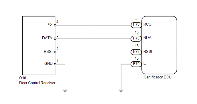
WIRING DIAGRAM
CAUTION / NOTICE / HINT
NOTICE:
- When replacing or inspecting the door control receiver and wire harness, do not change the position or length of the wire harness. If the wire harness is too close to the door control receiver, entry and wireless function performance may be affected.
- Before performing the inspection, check that there are no problems related to the CAN communication system.
- When using the Techstream with the engine switch off to troubleshoot: Connect the Techstream to the DLC3 and turn a courtesy light switch on and off at 1.5-second intervals until communication between the tester and vehicle begins.
- Before replacing the certification ECU, refer to the engine immobiliser
system (w/ Smart Key System) (See page
.gif)
).
PROCEDURE
|
1. |
CHECK HARNESS AND CONNECTOR (DOOR CONTROL RECEIVER - CERTIFICATION ECU AND BODY GROUND) |
(a) Disconnect the O10 receiver connector.
(b) Disconnect the F79 and F78 ECU connectors.
(c) Measure the resistance according to the value(s) in the table below.
Standard Resistance:
|
Tester Connection |
Condition |
Specified Condition |
|---|---|---|
|
O10-2 (RSSI) - F78-16 (RSSI) |
Always |
Below 1 Ω |
|
O10-5 (DATA) - F78-15 (RDA) |
Always |
Below 1 Ω |
|
O10-4 (+5) - F78-5 (RCO) |
Always |
Below 1 Ω |
|
O10-1 (GND) - Body ground |
Always |
Below 1 Ω |
|
F79-15 (E) - Body ground |
Always |
Below 1 Ω |
|
O10-2 (RSSI) or F78-16 (RSSI) - Body ground |
Always |
10 kΩ or higher |
|
O10-5 (DATA) or F78-15 (RDA) - Body ground |
Always |
10 kΩ or higher |
|
O10-4 (+5) or F78-5 (RCO) - Body ground |
Always |
10 kΩ or higher |
| NG | .gif) |
REPAIR OR REPLACE HARNESS OR CONNECTOR |
|
.gif)
|
2. |
CHECK CERTIFICATION ECU |
(a) Measure the voltage according to the value(s) in the table below.
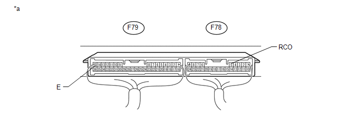 Text in Illustration
|
*a |
Component with harness connected (Certification ECU) |
- |
- |
Standard Voltage:
|
Tester Connection |
Switch Condition |
Specified Condition |
|---|---|---|
|
F78-5 (RCO) - F79-15 (E) |
Engine switch off, all doors closed and transmitter switch not pressed → pressed |
Below 1 V → 4.5 to 5.5 V |
| NG | |
REPLACE CERTIFICATION ECU |
|
|
3. |
REPLACE DOOR CONTROL RECEIVER |
(a) Temporarily replace the door control receiver with a new or normally functioning
one (See page ).
|
|
4. |
CLEAR DTC |
(a) Clear the DTCs (See page ).
|
|
5. |
CHECK FOR DTC |
(a) Check for DTCs (See page ).
OK:
DTC B1242 is not output.
| OK | |
END (DOOR CONTROL RECEIVER IS DEFECTIVE) |
| NG | |
REPLACE CERTIFICATION ECU |
 Diagnostic Trouble Code Chart
DIAGNOSTIC TROUBLE CODE CHART
HINT:
If a trouble code is output during the DTC check, inspect the trouble areas listed
for that code. For details of the code, refer to the "See page" bel ...
 No Answer-Back
DESCRIPTION
In some cases, the wireless door lock control functions are normal but the hazard
warning light and/or wireless door lock buzzer answer-back function(s) does not
operate. In such case ...
Other materials about Toyota 4Runner:
Removal
REMOVAL
PROCEDURE
1. REMOVE PARK/NEUTRAL POSITION SWITCH ASSEMBLY
(a) Disconnect the switch connector.
(b) Using a screwdriver, bend the tabs of the lock washer.
(c) Remove the lock nut and l ...
ECU Initial Setting Incomplete (C120A)
DESCRIPTION
w/ Downhill Assist Control or w/ Crawl Control:
When the master cylinder solenoid (skid control ECU) is replaced, the master
cylinder solenoid (skid control ECU) must be informed that the vehicle is equipped
with downhill assist control and/o ...

0.0275