Toyota 4Runner: System Diagram
SYSTEM DIAGRAM
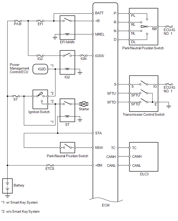
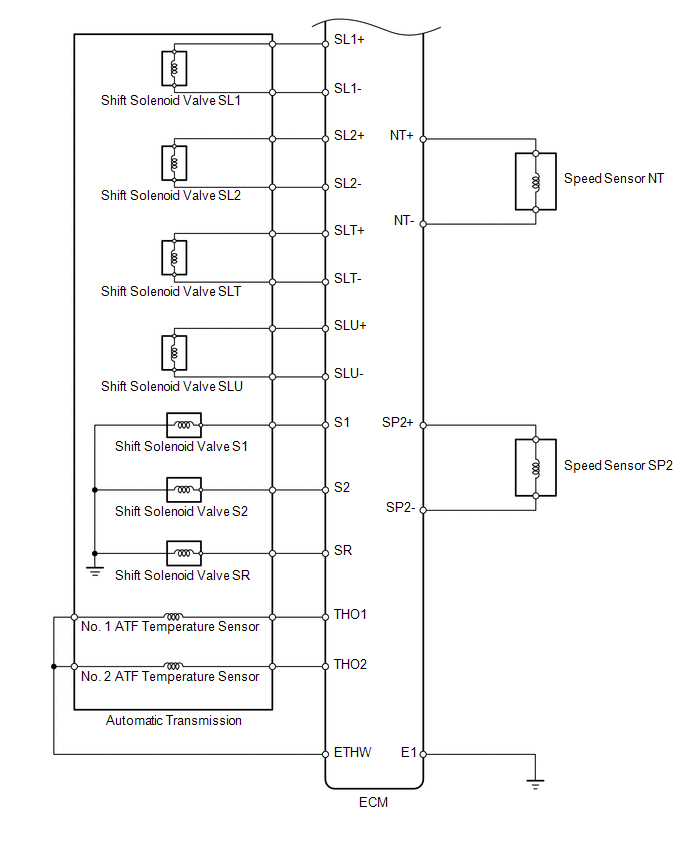
The configuration of the electronic control system for the A750E automatic transmission is as shown in the following chart.
 Parts Location
PARTS LOCATION
ILLUSTRATION
ILLUSTRATION
...
 System Description
SYSTEM DESCRIPTION
1. SYSTEM DESCRIPTION
(a) The Electronic Controlled Automatic Transmission (ECT) is an automatic transmission
that electronically controls shift timing using the Engine Control ...
Other materials about Toyota 4Runner:
Transmission Wire
Components
COMPONENTS
ILLUSTRATION
Removal
REMOVAL
PROCEDURE
1. DRAIN AUTOMATIC TRANSMISSION FLUID
(a) Remove the drain plug and gasket, and drain ATF.
(b) Install a new gasket and the drain plug.
Torque:
20 N·m {204 kgf·cm, 15 ft·lbf}
2. ...
Removal
REMOVAL
CAUTION / NOTICE / HINT
HINT:
Use the same procedure for both the RH and LH sides.
The procedure listed below is for the LH side.
PROCEDURE
1. REMOVE FRONT BUMPER COVER (w/o Intuitive Parking Assist System)
(See page )
2. REMO ...
© 2016-2025 | www.to4runner.net


0.009
0.009