Toyota 4Runner: Transmission Wire
Components
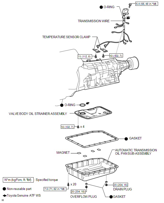
COMPONENTS
ILLUSTRATION
Removal
REMOVAL
PROCEDURE
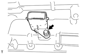
1. DRAIN AUTOMATIC TRANSMISSION FLUID
(a) Remove the drain plug and gasket, and drain ATF.
(b) Install a new gasket and the drain plug.
Torque:
20 N·m {204 kgf·cm, 15 ft·lbf}
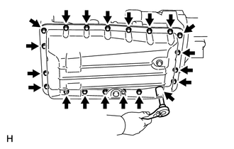
2. REMOVE AUTOMATIC TRANSMISSION OIL PAN SUB-ASSEMBLY
|
(a) Remove the 20 bolts, oil pan and gasket from the transmission. NOTICE: Some fluid will remain in the oil pan. Remove all the pan bolts, and carefully remove the oil pan assembly. |
|
(b) Examine the particles in the pan.
(1) Remove the 4 magnets and use them to collect steel particles. Carefully inspect the foreign matter and particles in the pan and on the magnets to anticipate the type of wear you will find in the transmission.
Steel (magnetic): bearing, gear and clutch plate wear
Brass (non-magnetic): bush wear
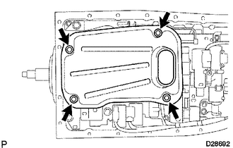
3. REMOVE VALVE BODY OIL STRAINER ASSEMBLY
|
(a) Remove the 4 bolts and oil strainer. NOTICE: Be careful as some fluid may leak out of the oil strainer. |
|
(b) Remove the O-ring from the oil strainer.
4. DISCONNECT TRANSMISSION WIRE
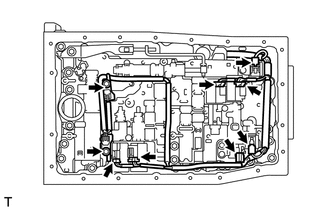
(a) Remove the 2 bolts and 2 temperature sensor clamps.
(b) Disconnect the 2 ATF temperature sensors.
(c) Disconnect the 7 connectors from the solenoid valves.
5. REMOVE TRANSMISSION WIRE
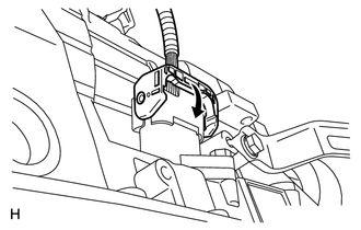
(a) Disconnect the wire connector.
(1) Detach the claw, press down the lever, and then disconnect the transmission wire connector.
|
(b) Remove the bolt and pull out the transmission wire. |
|
Inspection
INSPECTION
PROCEDURE
1. INSPECT TRANSMISSION WIRE (ATF TEMPERATURE SENSOR)
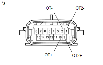
(a) Measure the resistance according to the value(s) in the table below.
Standard resistance:
|
Tester Connection |
ATF Temperature |
Specified Condition |
|---|---|---|
|
2 (OT-) - 10 (OT+) |
10°C (50°F) |
5 to 8 kΩ |
|
2 (OT-) - 10 (OT+) |
25°C (77°F) |
2.5 to 4.5 kΩ |
|
2 (OT-) - 10 (OT+) |
110°C (230°F) |
0.22 to 0.28 kΩ |
|
1 (OT2-) - 9 (OT2+) |
10°C (50°F) |
5 to 8 kΩ |
|
1 (OT2-) - 9 (OT2+) |
25°C (77°F) |
2.5 to 4.5 kΩ |
|
1 (OT2-) - 9 (OT2+) |
110°C (230°F) |
0.22 to 0.28 kΩ |
|
*a |
Component without harness connected (Transmission Wire) |
HINT:
If the resistance is out of the specified range at one of the ATF temperatures shown in the table below, the driveability of the vehicle may decrease.
Resistance (Reference):
|
ATF Temperature |
Specified Condition |
|---|---|
|
10°C (50°F) |
5 to 8 kΩ |
|
25°C (77°F) |
2.5 to 4.5 kΩ |
|
110°C (230°F) |
0.22 to 0.28 kΩ |
If the result is not as specified, replace the transmission wire.
Installation
INSTALLATION
PROCEDURE
1. INSTALL TRANSMISSION WIRE
(a) Coat a new O-ring with ATF and install it to the transmission wire connector.
(b) Install the transmission wire with the bolt.
Torque:
5.4 N·m {55 kgf·cm, 48 in·lbf}
|
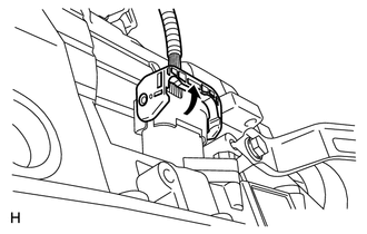
(c) Connect the transmission wire connector. HINT: Push up the lever until the claw of the transmission wire connector makes a connection sound. |
|
2. CONNECT TRANSMISSION WIRE
|
(a) Connect the 7 connectors to the solenoid valves. |
|
.png)
(b) Connect the 2 ATF temperature sensors with the 2 clamps and 2 bolts.
Torque:
for bolt A :
10 N·m {102 kgf·cm, 7 ft·lbf}
for bolt B :
11 N·m {112 kgf·cm, 8 ft·lbf}
Text in Illustration|
*1 |
Orange |
|
*2 |
Blue |
HINT:
Each bolt length is indicated below.
12 mm (0.472 in.) for bolt A
36 mm (1.41 in.) for bolt B
3. INSTALL VALVE BODY OIL STRAINER ASSEMBLY
(a) Coat a new O-ring with ATF and install it to the oil strainer.
(b) Install the oil strainer with the 4 bolts.
Torque:
10 N·m {102 kgf·cm, 7 ft·lbf}
4. INSTALL AUTOMATIC TRANSMISSION OIL PAN SUB-ASSEMBLY
NOTICE:
Remove the gasket and be careful not to spill oil on the contacting surfaces of the transmission case and oil pan.
(a) Install a new gasket and the oil pan with the 20 bolts.
Torque:
7.0 N·m {71 kgf·cm, 62 in·lbf}
5. ADD AUTOMATIC TRANSMISSION FLUID
(a) Add automatic transmission fluid (see page
.gif) ).
).
 Transmission Control Cable
Components
COMPONENTS
ILLUSTRATION
Removal
REMOVAL
PROCEDURE
1. REMOVE CONSOLE BOX ASSEMBLY
(a) Remove the console box assembly (See page
).
2. REMOVE TRANSMISSION CONTROL CABLE ASSEM ...

Other materials about Toyota 4Runner:
Installation
INSTALLATION
PROCEDURE
1. INSTALL CENTER CONTROL ABSORBER BRACKET LH
(a) Install the center control absorber bracket with the 2 bolts.
Torque:
29 N·m {296 kgf·cm, 21 ft·lbf}
2. INSTALL CENTER CONTROL ABSORBER BRACKET RH
HINT:
Use the same procedure ...
Inspection
INSPECTION
PROCEDURE
1. INSPECT TRANSMISSION CONTROL SWITCH
(a) Measure the resistance according to the value(s) in the table below.
Standard Resistance:
Tester Connection
Condition
Specified Condition
...
0.0255