Toyota 4Runner: 4WD Control ECU Communication Stop Mode
DESCRIPTION
|
Detection Item |
Symptom |
Trouble Area |
|---|---|---|
|
4WD Control ECU Communication Stop Mode |
Either condition is met:
|
|
HINT:
For vehicles with four wheel drive only.
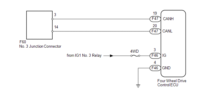
WIRING DIAGRAM
CAUTION / NOTICE / HINT
NOTICE:
Inspect the fuses for circuits related to this system before performing the following inspection procedure.
HINT:
Operating the ignition switch, any switches or any doors triggers related ECU and sensor communication with the CAN, which causes resistance variation.
PROCEDURE
|
1. |
DISCONNECT CABLE FROM NEGATIVE BATTERY TERMINAL |
(a) Disconnect the cable from the negative (-) battery terminal before measuring the resistances of the main wire and branch wire.
CAUTION:
Wait at least 90 seconds after disconnecting the cable from the negative (-) battery terminal to disable the SRS system.
NOTICE:
When disconnecting the cable, some systems need to be initialized after the cable
is reconnected (See page .gif) ).
).
|
.gif)
|
2. |
CHECK FOR OPEN IN CAN BUS WIRE (FOUR WHEEL DRIVE CONTROL ECU BRANCH WIRE) |
|
(a) Disconnect the F47 four wheel drive control ECU connector. |
|
(b) Measure the resistance according to the value(s) in the table below.
Standard Resistance:
|
Tester Connection |
Switch Condition |
Specified Condition |
|---|---|---|
|
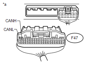
F47-19 (CANH) - F47-20 (CANL) |
Ignition switch off |
54 to 69 Ω |
|
*a |
Rear view of wire harness connector (to Four Wheel Drive Control ECU) |
| NG | .gif) |
REPAIR OR REPLACE FOUR WHEEL DRIVE CONTROL ECU BRANCH WIRE OR CONNECTOR (CANH, CANL) |
|
|
3. |
CHECK HARNESS AND CONNECTOR (FOUR WHEEL DRIVE CONTROL ECU - BATTERY AND BODY GROUND) |
|
(a) Connect the cable to the negative (-) battery terminal. NOTICE: When disconnecting the cable, some systems need to be initialized after
the cable is reconnected (See page |
|
(b) Disconnect the F46 four wheel drive control ECU connector.
(c) Measure the resistance according to the value(s) in the table below.
Standard Resistance:
|
Tester Connection |
Condition |
Specified Condition |
|---|---|---|
|
F46-4 (GND) - Body ground |
Always |
Below 1 Ω |
(d) Measure the voltage according to the value(s) in the table below.
Standard Voltage:
|
Tester Connection |
Switch Condition |
Specified Condition |
|---|---|---|
|
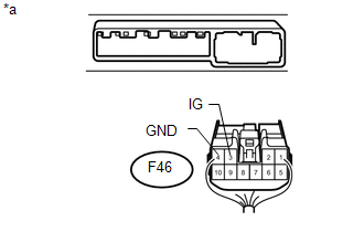
F46-3 (IG) - Body ground |
Ignition switch ON |
11 to 14 V |
|
*a |
Rear view of wire harness connector (to Four Wheel Drive Control ECU) |
|
Result |
Proceed to |
|---|---|
|
OK (for VF2A) |
A |
|
OK (for VF4BM) |
B |
|
OK (for VF2BM) |
C |
|
NG |
D |
| A | |
REPLACE NO. 2 FOUR WHEEL DRIVE CONTROL ECU |
| B | |
REPLACE NO. 2 FOUR WHEEL DRIVE CONTROL ECU |
| C | |
REPLACE NO. 2 FOUR WHEEL DRIVE CONTROL ECU |
| D | |
REPAIR OR REPLACE HARNESS OR CONNECTOR |
 Center Airbag Sensor Communication Stop Mode
DESCRIPTION
Detection Item
Symptom
Trouble Area
Center Airbag Sensor Communication Stop Mode
Either condition is met:
" ...
 Suspension Control ECU Communication Stop Mode
DESCRIPTION
Detection Item
Symptom
Trouble Area
Suspension Control ECU Communication Stop Mode
Either condition is met:
&quo ...
Other materials about Toyota 4Runner:
Vehicle Lift And Support Locations
VEHICLE LIFT AND SUPPORT LOCATIONS
1. NOTICE ABOUT VEHICLE CONDITION WHEN RAISING VEHICLE
(a) The vehicle must be unloaded before jacking up or raising the vehicle. Never
jack up or raise a heavily loaded vehicle.
(b) When removing any heavy components li ...
Installation
INSTALLATION
PROCEDURE
1. INSTALL PARK/NEUTRAL POSITION SWITCH ASSEMBLY
(a) Install the switch to the manual valve shaft.
(b) Temporarily install the bolt.
(c) Install a new lock washer and the nut ...

0.007