Toyota 4Runner: Automatic Running Board Switch
Components
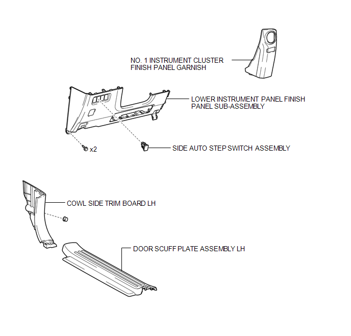
COMPONENTS
ILLUSTRATION
Removal
REMOVAL
PROCEDURE
1. REMOVE DOOR SCUFF PLATE ASSEMBLY LH
.gif)
2. REMOVE COWL SIDE TRIM BOARD LH
3. REMOVE NO. 1 INSTRUMENT CLUSTER FINISH PANEL GARNISH
4. REMOVE LOWER INSTRUMENT PANEL FINISH PANEL SUB-ASSEMBLY
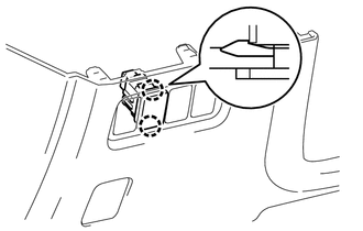
5. REMOVE SIDE AUTO STEP SWITCH ASSEMBLY
|
(a) Disengage the 2 claws and remove the side auto step switch assembly. |
|
Inspection
INSPECTION
PROCEDURE
1. INSPECT SIDE AUTO STEP SWITCH ASSEMBLY
|
(a) Measure the resistance according to the value(s) in the table below. Standard Resistance:
|
|
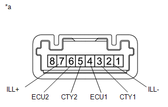
(b) Apply battery voltage to the connector and check the LED illumination.
OK:
|
Measurement Condition |
Specified Condition |
|---|---|
|
Battery positive (+) → Terminal 7 (ILL+) Battery negative (-) → Terminal 2 (ILL-) |
LED illuminates |
Installation
INSTALLATION
CAUTION / NOTICE / HINT
HINT:
A bolt without a torque specification is shown in the standard bolt chart (See
page .gif) ).
).
PROCEDURE
1. INSTALL SIDE AUTO STEP SWITCH ASSEMBLY
(a) Engage the 2 claws and install the side auto step switch assembly.
2. INSTALL LOWER INSTRUMENT PANEL FINISH PANEL SUB-ASSEMBLY
3. INSTALL NO. 1 INSTRUMENT CLUSTER FINISH PANEL GARNISH
4. INSTALL COWL SIDE TRIM BOARD LH
5. INSTALL DOOR SCUFF PLATE ASSEMBLY LH
 Removal
REMOVAL
PROCEDURE
1. DISCONNECT CABLE FROM NEGATIVE BATTERY TERMINAL
CAUTION:
Wait at least 90 seconds after disconnecting the cable from the negative (-)
battery terminal to disable the SRS sys ...

Other materials about Toyota 4Runner:
Mute Signal Circuit between Stereo Component Amplifier and Telematics Transceiver
DESCRIPTION
The DCM (telematics transceiver) sends a mute signal to the stereo component
amplifier assembly.
The stereo component amplifier assembly controls the volume according to the
mute signal from the DCM (telematics transceiver).
WIRING DIAGRAM
...
Reassembly
REASSEMBLY
PROCEDURE
1. INSTALL STEERING RACK END SUB-ASSEMBLY
(a) Temporarily install the 2 steering rack ends to the steering rack.
(b) Fill up the ball joints of the steering rack ends with MP grease.
(c) Using SST, install the steering rack ...

0.0072