Toyota 4Runner: Disassembly
DISASSEMBLY
PROCEDURE
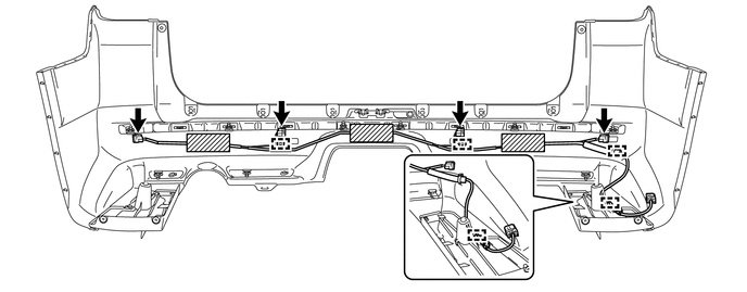
1. REMOVE NO. 3 FLOOR WIRE
(a) Disconnect the 4 connectors and remove the 3 pieces of tape.
(b) Detach the 4 clamps to remove the No. 3 floor wire.
2. REMOVE REAR BUMPER SIDE BRACKET LH
|
(a) Remove the clip and 2 screws. |
|
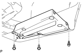
(b) Detach the guide to remove the rear bumper side bracket LH.
3. REMOVE REAR BUMPER SIDE BRACKET RH
HINT:
Use the same procedure as for the LH side.
4. REMOVE REAR BUMPER PLATE LH
|
(a) Remove the 2 outside moulding retainers. |
|
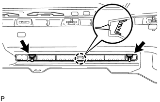
(b) Detach the claw to remove the rear bumper plate LH.
5. REMOVE REAR BUMPER PLATE RH
|
(a) Remove the outside moulding retainer. |
|
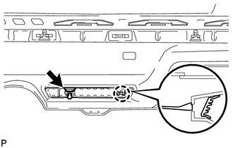
(b) Detach the claw to remove the rear bumper plate RH.
6. REMOVE NO. 1 REAR BUMPER PLATE
|
(a) Remove the outside moulding retainer. |
|
(b) Detach the claw to remove the No. 1 rear bumper plate.
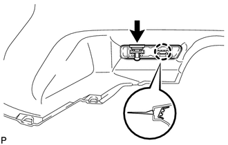
7. REMOVE REAR BUMPER CENTER MOULDING
(a) Remove the 6 outside moulding retainers.
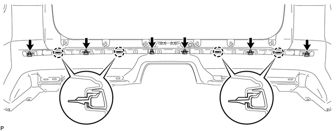
(b) Detach the 4 claws to remove the rear bumper center moulding.
8. REMOVE NO. 1 ULTRASONIC SENSOR
.gif)
9. REMOVE ULTRASONIC SENSOR CLIP
10. REMOVE NO. 2 ULTRASONIC SENSOR RETAINER
11. REMOVE NO. 1 ULTRASONIC SENSOR RETAINER
 Removal
REMOVAL
PROCEDURE
1. REMOVE JACK BOX HOLE COVER
2. REMOVE REAR QUARTER PANEL MUDGUARD LH
3. REMOVE REAR QUARTER PANEL MUDGUARD RH
HINT:
Use the same procedure as for the LH side.
4. REMOV ...
 Reassembly
REASSEMBLY
PROCEDURE
1. INSTALL NO. 1 ULTRASONIC SENSOR RETAINER
2. INSTALL NO. 2 ULTRASONIC SENSOR RETAINER
3. INSTALL ULTRASONIC SENSOR CLIP
4. INSTALL NO. 1 ULTRASONIC SENSOR
5. I ...
Other materials about Toyota 4Runner:
Sound Signal Circuit between Navigation Receiver Assembly and Stereo Component
Amplifier
DESCRIPTION
The navigation receiver assembly sends a sound signal to the stereo component
amplifier assembly via the sound signal circuit.
The sound signal that has been sent is amplified by the stereo component amplifier
assembly, and then is sent to th ...
Front passenger occupant classification system
Your vehicle is equipped with a front passenger occupant classification
system. This system detects the conditions of the front passenger seat and
activates or deactivates the devices for the front passenger.
1. SRS warning light
2. Front passenger’ ...

0.0202