Toyota 4Runner: Removal
REMOVAL
PROCEDURE
1. REMOVE JACK BOX HOLE COVER
.gif)
2. REMOVE REAR QUARTER PANEL MUDGUARD LH
3. REMOVE REAR QUARTER PANEL MUDGUARD RH
HINT:
Use the same procedure as for the LH side.
4. REMOVE REAR BUMPER COVER
(a) Remove the 2 bolts and 2 screws.
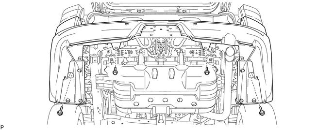
(b) Put protective tape around the rear bumper cover.
(c) Remove the 2 screws and 6 bolts.
(d) Detach the 18 claws to remove the rear bumper cover.
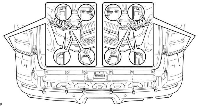 Text in Illustration
|
*1 |
Protective Tape |
- |
- |
(e) Disconnect the connector.
5. REMOVE REAR BUMPER ENERGY ABSORBER
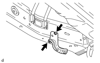
6. REMOVE REAR BUMPER BAR REINFORCEMENT LH
|
(a) Remove the 2 bolts and rear bumper bar reinforcement LH. |
|
7. REMOVE REAR BUMPER BAR REINFORCEMENT RH
HINT:
Use the same procedure as for the LH side.
8. REMOVE REAR BUMPER SIDE SUPPORT LH
9. REMOVE REAR BUMPER SIDE SUPPORT RH
HINT:
Use the same procedure as for the LH side.
10. REMOVE REAR COMBINATION LIGHT LENS AND BODY LH
11. REMOVE REAR COMBINATION LIGHT LENS AND BODY RH
HINT:
Use the same procedure as for the LH side.
12. REMOVE REAR BUMPER UPPER RETAINER LH
13. REMOVE REAR BUMPER UPPER RETAINER RH
HINT:
Use the same procedure as for the LH side.
14. REMOVE PINTLE HOOK SUPPORT TUBE SUB-ASSEMBLY (w/ Pintle Hook)
 Components
COMPONENTS
ILLUSTRATION
ILLUSTRATION
ILLUSTRATION
ILLUSTRATION
...
 Disassembly
DISASSEMBLY
PROCEDURE
1. REMOVE NO. 3 FLOOR WIRE
(a) Disconnect the 4 connectors and remove the 3 pieces of tape.
(b) Detach the 4 clamps to remove the No. 3 floor wire.
2. REMOVE REAR BUMPER S ...
Other materials about Toyota 4Runner:
Installation
INSTALLATION
PROCEDURE
1. INSTALL NO. 1 STEREO JACK ADAPTER ASSEMBLY
(a) Attach the 2 claws to install the No. 1 stereo jack adapter assembly.
2. INSTALL LOWER CENTER INSTRUMENT CLUSTER FINISH PANEL SUB-ASSEMBLY (w/o Climate
Control Seat System)
3. I ...
Data List / Active Test
DATA LIST / ACTIVE TEST
1. ACTIVE TEST
HINT:
Using the Techstream to perform Active Tests allows relays, VSVs, actuators and
other items to be operated without removing any parts. This non-intrusive functional
inspection can be very useful because inter ...

0.009