Toyota 4Runner: Dtc Check / Clear
DTC CHECK / CLEAR
1. CHECK DTC (USING TECHSTREAM)
(a) Turn the ignition switch off.
(b) Connect the Techstream to the DLC3.
(c) Turn the ignition switch to ON.
(d) Turn the Techstream on.
(e) Enter the following menus: Chassis / Tire Pressure Monitor / Trouble Codes.
(f) Read the DTCs following the prompts on the Techstream screen.
HINT:
Refer to the Techstream operator's manual for further details.
2. CHECK DTC (USING SST CHECK WIRE)
(a) Turn the ignition switch off.
(b) Using SST, connect terminals 13 (TC) and 4 (CG) of the DLC3.
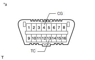
SST: 09843-18040
Text in Illustration|
*a |
Front view of DLC3 |
(c) Turn the ignition switch to ON.
(d) Read and record any DTCs from the tire pressure warning light in the combination meter.
HINT:
- When only 1 DTC is stored, the light outputs the same code after an interval of 4.5 seconds. Example: When DTC 21 is stored, the light blinks twice, turns off for 1.5 seconds, blinks once, turns off for 4.5 seconds, and then repeats this output pattern.
- When 2 or more DTCs are stored, the light outputs the codes with an interval of 2.5 seconds between each different code and the output of all codes repeats after an interval of 4.5 seconds.
- If the tire pressure warning light does not output any DTCs or the tire
pressure warning light turns on and goes off repeatedly at 0.25 second intervals,
inspect the tire pressure warning light circuit or TC and CG terminal circuit.
Trouble Area
See page
Tire pressure warning light circuit
.gif)
TC and CG terminal circuit
- If 2 or more malfunctions are indicated at the same time, the lowest numbered DTC is output first.
(e) Refer to the Diagnostic Trouble Code Chart (See page
) for DTC information.
(f) After completing the check, turn the ignition switch off and remove SST from the DLC3.
SST: 09843-18040
3. CLEAR DTC
HINT:
After repairing the malfunctions, clear the DTCs.
(a) Turn the ignition switch off.
(b) Connect the Techstream to the DLC3.
(c) Turn the ignition switch to ON.
(d) Turn the Techstream on.
(e) Enter the following menus: Chassis / Tire Pressure Monitor / Trouble Codes.
(f) Clear the DTCs following the prompts on the Techstream screen.
HINT:
Refer to the Techstream operator's manual for further details.
 Data List / Active Test
DATA LIST / ACTIVE TEST
1. READ DATA LIST
HINT:
Using the Techstream to read the Data List allows the values or states of switches,
sensors, actuators and other items to be read without removing ...
 Diagnostic Trouble Code Chart
DIAGNOSTIC TROUBLE CODE CHART
Tire pressure warning system
DTC Code
Detection Item
See page
C2111/11
Transmitter ID1 Operation Stop
...
Other materials about Toyota 4Runner:
Installation
INSTALLATION
PROCEDURE
1. INSTALL REAR WIPER MOTOR AND BRACKET ASSEMBLY
(a) Attach the 2 guides and temporally install the rear wiper motor and
bracket assembly with the 3 bolts.
(b) Tighten the ...
Disassembly
DISASSEMBLY
PROCEDURE
1. REMOVE AUTOMATIC TRANSMISSION CASE O-RING
(a) Remove the O-ring from the oil pump assembly.
2. FIX OIL PUMP ASSEMBLY
(a) Place the oil pump body on the torque convert ...

0.0071