Toyota 4Runner: ECM Communication Stop Mode
DESCRIPTION
|
Detection Item |
Symptom |
Trouble Area |
|---|---|---|
|
ECM Communication Stop Mode |
Either condition is met:
|
|
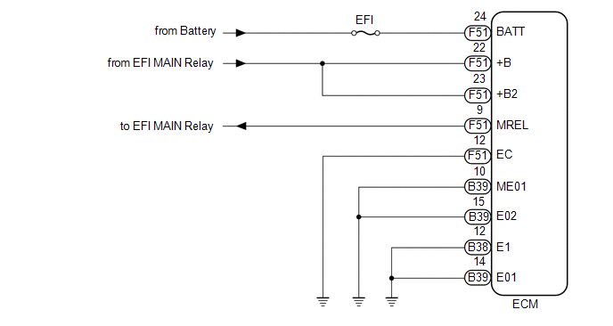
WIRING DIAGRAM
CAUTION / NOTICE / HINT
NOTICE:
Inspect the fuses for circuits related to this system before performing the following inspection procedure.
PROCEDURE
|
1. |
CHECK HARNESS AND CONNECTOR (ECM - BATTERY AND BODY GROUND) |
(a) Disconnect the B38, B39 and F51 ECM connectors.
.png) Text in Illustration
Text in Illustration
|
*a |
Front view of wire harness connector (to ECM) |
- |
- |
(b) Measure the resistance according to the value(s) in the table below.
Standard Resistance:
|
Tester Connection |
Condition |
Specified Condition |
|---|---|---|
|
B38-12 (E1) - Body ground |
Always |
Below 1 Ω |
|
B39-10 (ME01) - Body ground |
Always |
Below 1 Ω |
|
B39-14 (E01) - Body ground |
Always |
Below 1 Ω |
|
B39-15 (E02) - Body ground |
Always |
Below 1 Ω |
|
F51-12 (EC) - Body ground |
Always |
Below 1 Ω |
(c) Measure the voltage according to the value(s) in the table below.
Standard Voltage:
|
Tester Connection |
Condition |
Specified Condition |
|---|---|---|
|
F51-24 (BATT) - Body ground |
Always |
11 to 14 V |
|
F51-23 (+B2) - Body ground |
Battery positive (+) voltage applied to terminal F51-9 (MREL) |
11 to 14 V |
|
F51-22 (+B) - Body ground |
Battery positive (+) voltage applied to terminal F51-9 (MREL) |
11 to 14 V |
| OK | .gif) |
REPLACE ECM |
| NG | |
REPAIR OR REPLACE HARNESS OR CONNECTOR |
 Yaw Rate Sensor Communication Stop Mode
DESCRIPTION
Detection Item
Symptom
Trouble Area
Yaw Rate Sensor Communication Stop Mode
Either condition is met:
"Yaw R ...
 Main Body ECU Communication Stop Mode
DESCRIPTION
Detection Item
Symptom
Trouble Area
Main Body ECU Communication Stop Mode
Either condition is met:
"Main Bo ...
Other materials about Toyota 4Runner:
Side Step
Components
COMPONENTS
ILLUSTRATION
ILLUSTRATION
Disassembly
DISASSEMBLY
CAUTION / NOTICE / HINT
HINT:
Use the same procedure for the RH and LH sides.
The procedure listed below is for the LH side.
PROCEDURE
1. REMOVE SIDE ST ...
Removal
REMOVAL
PROCEDURE
1. REMOVE FRONT BUMPER COVER (w/o Intuitive Parking Assist System)
(See Page )
2. REMOVE FRONT BUMPER COVER (w/ Intuitive Parking Assist System)
(See Page )
3. REMOVE HIGH PITCHED HORN ASSEMBLY
4. REMOVE RADIATOR GRILLE BRACKET
...

0.0078