Toyota 4Runner: Main Body ECU Communication Stop Mode
DESCRIPTION
|
Detection Item |
Symptom |
Trouble Area |
|---|---|---|
|
Main Body ECU Communication Stop Mode |
Either condition is met:
|
|
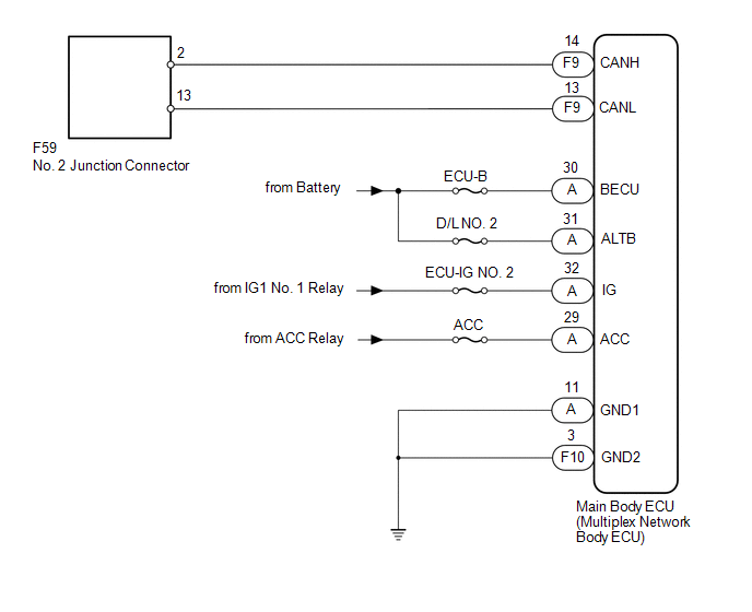
WIRING DIAGRAM
CAUTION / NOTICE / HINT
NOTICE:
Inspect the fuses for circuits related to this system before performing the following inspection procedure.
HINT:
Operating the ignition switch, any switches or any doors triggers related ECU and sensor communication with the CAN, which causes resistance variation.
PROCEDURE
|
1. |
DISCONNECT CABLE FROM NEGATIVE BATTERY TERMINAL |
(a) Disconnect the cable from the negative (-) battery terminal before measuring the resistances of the main wire and branch wire.
CAUTION:
Wait at least 90 seconds after disconnecting the cable from the negative (-) battery terminal to disable the SRS system.
NOTICE:
When disconnecting the cable, some systems need to be initialized after the cable
is reconnected (See page .gif) ).
).
|
.gif)
|
2. |
CHECK FOR OPEN IN CAN BUS WIRE (MAIN BODY ECU BRANCH WIRE) |
|
(a) Disconnect the F9 main body ECU (multiplex network body ECU) connector. |
|
(b) Measure the resistance according to the value(s) in the table below.
Standard Resistance:
|
Tester Connection |
Switch Condition |
Specified Condition |
|---|---|---|
|
F9-14 (CANH) - F9-13 (CANL) |
Ignition switch off |
54 to 69 Ω |
|
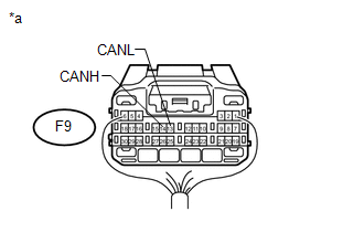
*a |
Rear view of wire harness connector (to Main Body ECU [Multiplex Network Body ECU]) |
| NG | .gif) |
REPAIR OR REPLACE MAIN BODY ECU BRANCH WIRE OR CONNECTOR (CANH, CANL) |
|
|
3. |
CHECK HARNESS AND CONNECTOR (MAIN BODY ECU - BATTERY AND BODY GROUND) |
(a) Connect the cable to the negative (-) battery terminal.
NOTICE:
When disconnecting the cable, some systems need to be initialized after the cable
is reconnected (See page ).
.png) Text in Illustration
Text in Illustration
|
*a |
Rear view of wire harness connector (to Main Body ECU [Multiplex Network Body ECU]) |
*b |
Front view of wire harness connector (to Main Body ECU [Multiplex Network Body ECU]) |
(b) Remove the main body ECU (multiplex network body ECU) (See page
).
(c) Measure the resistance according to the value(s) in the table below.
Standard Resistance:
|
Tester Connection |
Condition |
Specified Condition |
|---|---|---|
|
F10-3 (GND2) - Body ground |
Always |
Below 1 Ω |
|
A-11 (GND1) - Body ground |
Always |
Below 1 Ω |
(d) Measure the voltage according to the value(s) in the table below.
Standard Voltage:
|
Tester Connection |
Switch Condition |
Specified Condition |
|---|---|---|
|
A-32 (IG) - Body ground |
Ignition switch ON |
11 to 14 V |
|
A-31 (ALTB) - Body ground |
Always |
11 to 14 V |
|
A-30 (BECU) - Body ground |
Always |
11 to 14 V |
|
A-29 (ACC) - Body ground |
Ignition switch ACC |
11 to 14 V |
| OK | |
REPLACE MAIN BODY ECU (MULTIPLEX NETWORK BODY ECU) |
| NG | |
REPAIR OR REPLACE HARNESS OR CONNECTOR |
 ECM Communication Stop Mode
DESCRIPTION
Detection Item
Symptom
Trouble Area
ECM Communication Stop Mode
Either condition is met:
"ECM (Engine)" ...
 Power Management Control ECU Communication Stop Mode
DESCRIPTION
Detection Item
Symptom
Trouble Area
Power Management Control ECU Communication Stop Mode
Either condition is met:
...
Other materials about Toyota 4Runner:
Open Circuit in IG1/IG2 Power Source Circuit (C1242)
DESCRIPTION
If there is a problem with the master cylinder solenoid (skid control ECU) power
supply circuit, the skid control ECU stores DTCs and prohibits operation under the
fail-safe function.
If the voltage supplied to the IG2 terminal is within the ...
How To Proceed With Troubleshooting
CAUTION / NOTICE / HINT
HINT:
Use these procedures to troubleshoot the tire pressure warning system.
*: Use the Techstream.
PROCEDURE
1.
VEHICLE BROUGHT TO WORKSHOP
NEXT
...

0.0237