Toyota 4Runner: Front Axle Hub Bolt
Components
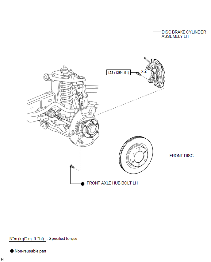
COMPONENTS
ILLUSTRATION
Replacement
REPLACEMENT
CAUTION / NOTICE / HINT
HINT:
- Use the same procedure for the RH and LH sides.
- The procedure listed below is for the LH side.
PROCEDURE
1. REMOVE FRONT WHEEL
2. REMOVE DISC BRAKE CYLINDER ASSEMBLY LH
.gif)
3. REMOVE FRONT DISC
4. REMOVE FRONT AXLE HUB BOLT LH
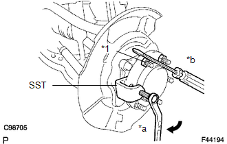
(a) Using SST and a screwdriver or equivalent to hold the axle hub, remove the front axle hub bolt.
SST: 09611-12010
Text in Illustration|
*1 |
Nut |
|
*a |
Turn |
|
*b |
Hold |
NOTICE:
Do not damage the threads of the hub bolt.
5. INSTALL FRONT AXLE HUB BOLT LH
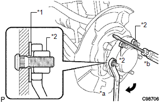
(a) Insert a new hub bolt.
(b) Temporarily install a washer and hub nut to the hub bolt as shown in the illustration.
Text in Illustration|
*1 |
Washer |
|
*2 |
Nut |
|
*a |
Turn |
|
*b |
Hold |
NOTICE:
Install a hub nut to prevent damage to the hub bolt.
(c) Using a screwdriver or equivalent to hold the hub, turn the hub nut until the bottom surface of the hub bolt head touches the axle hub.
(d) Remove the hub nut and washer.
NOTICE:
Do not damage the threads of the hub bolt.
6. INSTALL FRONT DISC
7. INSTALL DISC BRAKE CYLINDER ASSEMBLY LH
8. INSTALL FRONT WHEEL
Torque:
for aluminum wheel :
103 N·m {1050 kgf·cm, 76 ft·lbf}
for steel wheel :
112 N·m {1142 kgf·cm, 83 ft·lbf}
 Inspection
INSPECTION
PROCEDURE
1. INSPECT DIFFERENTIAL LOCK SYSTEM
(a) Inspect the indicator light.
(1) Check that the indicator light lights up approximately 1 second after the
ignition switch is turne ...

Other materials about Toyota 4Runner:
Trailer towing
Your vehicle is designed primarily as a passenger-and-load-carrying
vehicle. Towing a trailer can have an adverse impact on handling, performance,
braking, durability, and fuel consumption. For your safety and the safety of
others, you must not overload ...
Installation
INSTALLATION
CAUTION / NOTICE / HINT
CAUTION:
Wear protective gloves. Sharp areas on the parts may injure your hands.
HINT:
Use the same procedure for the power seat RH and power seat LH sides.
The procedure listed below is for the power se ...

0.0243