Toyota 4Runner: Headlight Relay Circuit
DESCRIPTION
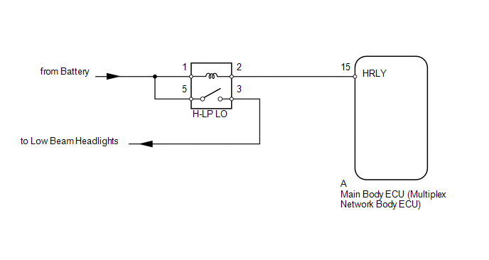
The main body ECU receives headlight dimmer switch information signals, and illuminates the low beam headlight.
WIRING DIAGRAM
CAUTION / NOTICE / HINT
NOTICE:
Inspect the fuses and bulbs for circuits related to this system before performing the following inspection procedure.
PROCEDURE
|
1. |
PERFORM ACTIVE TEST USING TECHSTREAM (HEADLIGHT RELAY) |
(a) Using the Techstream, perform the Active Test (See page
.gif) ).
).
Main Body
|
Tester Display |
Test Part |
Control Range |
Diagnostic Note |
|---|---|---|---|
|
Headlight Relay |
Low beam headlight relay |
ON/OFF |
- |
OK:
Headlight relay operates (low beam headlights illuminate).
| OK | .gif) |
PROCEED TO NEXT SUSPECTED AREA SHOWN IN PROBLEM SYMPTOMS TABLE |
|
.gif)
|
2. |
INSPECT HEADLIGHT RELAY (H-LP LO) |
|
(a) Remove the headlight relay from the engine room relay block, junction block. |
|
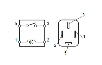
(b) Measure the resistance according to the value(s) in the table below.
Standard Resistance:
|
Tester Connection |
Condition |
Specified Condition |
|---|---|---|
|
3 - 5 |
Battery voltage not applied between terminals 1 and 2 |
10 kΩ or higher |
|
Battery voltage applied between terminals 1 and 2 |
Below 1 Ω |
| NG | |
REPLACE HEADLIGHT RELAY |
|
|
3. |
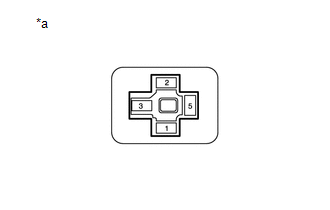
CHECK HARNESS AND CONNECTOR (BATTERY - HEADLIGHT RELAY [H-LP LO]) |
|
(a) Measure the voltage according to the value(s) in the table below. Standard Voltage:
|
|
| NG | |
REPAIR OR REPLACE HARNESS OR CONNECTOR |
|
|
4. |
CHECK HARNESS AND CONNECTOR (HEADLIGHT RELAY [H-LP LO] - MAIN BODY ECU) |
(a) Remove the main body ECU (See page ).
(b) Measure the resistance according to the value(s) in the table below.
Standard Resistance:
|
Tester Connection |
Condition |
Specified Condition |
|---|---|---|
|
Headlight relay terminal 2 - A-15 (HRLY) |
Always |
Below 1 Ω |
|
A-15 (HRLY) - Body ground |
Always |
10 kΩ or higher |
| OK | |
PROCEED TO NEXT SUSPECTED AREA SHOWN IN PROBLEM SYMPTOMS TABLE |
| NG | |
REPAIR OR REPLACE HARNESS OR CONNECTOR |
 Headlight Dimmer Switch Circuit
DESCRIPTION
The main body ECU receives the following signals:
Headlight dimmer switch tail, head, AUTO*, high or high flash signal
Front fog light switch signal
*: w/ Aut ...
 Headlight (HI-BEAM) Circuit
DESCRIPTION
The main body ECU (multiplex network body ECU) receives headlight dimmer switch
information signals, and illuminates the high beam headlight.
WIRING DIAGRAM
CAUTION / NOTICE / HINT
...
Other materials about Toyota 4Runner:
Removal
REMOVAL
PROCEDURE
1. REMOVE REAR NO. 1 SPOILER COVER
(a) Detach the 4 clips and remove the rear No. 1 spoiler cover.
2. REMOVE REAR SPOILER SUB-ASSEMBLY
(a) Remove the 4 grommets and 4 bolts.
...
Telephone Microphone Error (B1572)
DESCRIPTION
This DTC is stored when the DCM (Telematics Transceiver) detects a malfunction
in the telephone microphone assembly circuit.
DTC Code
DTC Detection Condition
Trouble Area
B1572
Curren ...

0.019