Toyota 4Runner: Headlight (HI-BEAM) Circuit
DESCRIPTION
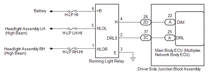
The main body ECU (multiplex network body ECU) receives headlight dimmer switch information signals, and illuminates the high beam headlight.
WIRING DIAGRAM
CAUTION / NOTICE / HINT
NOTICE:
Inspect the fuses and bulbs for circuits related to this system before performing the following inspection procedure.
PROCEDURE
|
1. |
PERFORM ACTIVE TEST USING TECHSTREAM (DAYTIME RUNNING LIGHT) |
(a) Using the Techstream, perform the Active Test (See page
.gif) ).
).
Main Body
|
Tester Display |
Test Part |
Control Range |
Diagnostic Note |
|---|---|---|---|
|
Daytime Running Light |
Running light relay |
ON/OFF |
- |
|
Head Light Hi |
Running light relay |
ON/OFF |
- |
OK:
Running light relay operates (high beam headlights illuminate).
| OK | .gif) |
PROCEED TO NEXT SUSPECTED AREA SHOWN IN PROBLEM SYMPTOMS TABLE |
|
.gif)
|
2. |
CHECK HARNESS AND CONNECTOR (BATTERY - RUNNING LIGHT RELAY) |
(a) Remove the running light relay from the engine room relay block, junction block.
(b) Measure the voltage according to the value(s) in the table below.
Standard Voltage:
|
Tester Connection |
Condition |
Specified Condition |
|---|---|---|
|
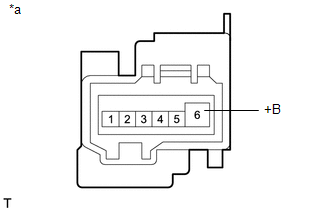
Running light relay terminal 6 (+B) - Body ground |
Always |
11 to 14 V |
|
*a |
Front view of wire harness connector (to Running Light Relay) |
| NG | |
REPAIR OR REPLACE HARNESS OR CONNECTOR |
|
|
3. |
CHECK HARNESS AND CONNECTOR (RUNNING LIGHT RELAY - DRIVER SIDE JUNCTION BLOCK ASSEMBLY) |
(a) Remove the running light relay from the engine room relay block, junction block.
(b) Disconnect the 2C and 2D driver side junction block assembly.
(c) Measure the resistance according to the value(s) in the table below.
Standard Resistance (Check for Open):
|
Tester Connection |
Condition |
Specified Condition |
|---|---|---|
|
Running light relay terminal 4 (H) - 2D-24 |
Always |
Below 1 Ω |
|
Running light relay terminal 2 (DRLS) - 2C-37 |
Always |
Below 1 Ω |
|
Running light relay terminal 3 (E) - Body ground |
Always |
Below 1 Ω |
Standard Resistance (Check for Short):
|
Tester Connection |
Condition |
Specified Condition |
|---|---|---|
|
Running light relay terminal 4 (H) or 2D-24 - Body ground |
Always |
10 kΩ or higher |
|
Running light relay terminal 2 (DRLS) or 2C-37 - Body ground |
Always |
10 kΩ or higher |
| NG | |
REPAIR OR REPLACE HARNESS OR CONNECTOR |
|
|
4. |
CHECK DRIVER SIDE JUNCTION BLOCK ASSEMBLY |
(a) Remove the driver side junction block assembly (See page
).
(b) Remove the main body ECU (multiplex network body ECU) from the driver side junction block assembly.
(c) Measure the resistance according to the value(s) in the table below.
Standard Resistance:
|
Tester Connection |
Condition |
Specified Condition |
|---|---|---|
|
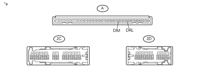
2D-24 - A-22 (DIM) |
Always |
Below 1 Ω |
|
2C-37 - A-25 (DRL) |
Always |
Below 1 Ω |
|
*a |
Component without harness connected (Driver Side Junction Block Assembly) |
- |
- |
| NG | |
REPLACE DRIVER SIDE JUNCTION BLOCK ASSEMBLY |
|
|
5. |
REPLACE RUNNING LIGHT RELAY |
(a) Replace the running light relay.
(b) Check that the daytime running lights operate normally (See page
).
OK:
The daytime running lights operate normally.
| OK | |
END (RUNNING LIGHT RELAY WAS DEFECTIVE) |
| NG | |
REPLACE MAIN BODY ECU (MULTIPLEX NETWORK BODY ECU) |
 Headlight Relay Circuit
DESCRIPTION
The main body ECU receives headlight dimmer switch information signals, and illuminates
the low beam headlight.
WIRING DIAGRAM
CAUTION / NOTICE / HINT
NOTICE:
Inspect the fuses an ...
 Front Fog Light Circuit
DESCRIPTION
The main body ECU receives headlight dimmer switch information signals, and illuminates
the front fog light.
WIRING DIAGRAM
CAUTION / NOTICE / HINT
NOTICE:
Inspect the fuses and b ...
Other materials about Toyota 4Runner:
Using the phone book
To enter the menu of each setting, follow the steps below:
• Adding a new phone number 1. “Phonebook” → 2. “Add Entry”
• Setting speed dial 1. “Phonebook” → 2. “Speed Dial (Set speed dial)”
• Changing a registered name 1. “Phon ...
VFC Solenoid Circuit (C15F0)
DESCRIPTION
This circuit supplies electric power to the power steering solenoid valve.
The power steering ECU assembly controls the output current to the power steering
solenoid valve in accordance with the steering angle signal, steering zero point
memo ...

0.0263