Toyota 4Runner: Front Fog Light Circuit
DESCRIPTION
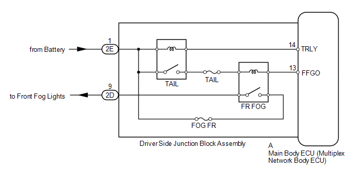
The main body ECU receives headlight dimmer switch information signals, and illuminates the front fog light.
WIRING DIAGRAM
CAUTION / NOTICE / HINT
NOTICE:
Inspect the fuses and bulbs for circuits related to this system before performing the following inspection procedure.
PROCEDURE
|
1. |
PERFORM ACTIVE TEST USING TECHSTREAM (FRONT FOG LIGHT RELAY) |
(a) Using the Techstream, perform the Active Test (See page
.gif) ).
).
Main Body
|
Tester Display |
Test Part |
Control Range |
Diagnostic Note |
|---|---|---|---|
|
Front Fog Light Relay |
Front fog light relay |
ON/OFF |
- |
OK:
Front fog light relay operates (front fog lights come on).
| OK | .gif) |
REPLACE MAIN BODY ECU (MULTIPLEX NETWORK BODY ECU) |
|
.gif)
|
2. |
CHECK MAIN BODY ECU (MULTIPLEX NETWORK BODY ECU) |
|
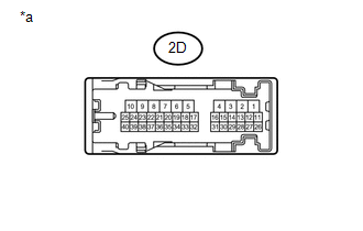
(a) Measure the voltage according to the value(s) in the table below. Standard Voltage:
|
|
| OK | |
REPAIR OR REPLACE HARNESS OR CONNECTOR (DRIVER SIDE JUNCTION BLOCK ASSEMBLY - FOG LIGHT ASSEMBLY) |
| NG | |
PROCEED TO NEXT SUSPECTED AREA SHOWN IN PROBLEM SYMPTOMS TABLE |
 Headlight (HI-BEAM) Circuit
DESCRIPTION
The main body ECU (multiplex network body ECU) receives headlight dimmer switch
information signals, and illuminates the high beam headlight.
WIRING DIAGRAM
CAUTION / NOTICE / HINT
...
 Taillight Relay Circuit
DESCRIPTION
The main body ECU receives headlight dimmer switch information signals, and illuminates
the clearance lights, taillights and license plate lights.
WIRING DIAGRAM
CAUTION / NOTICE / ...
Other materials about Toyota 4Runner:
Power Window Master Switch
Components
COMPONENTS
ILLUSTRATION
Removal
REMOVAL
PROCEDURE
1. REMOVE FRONT DOOR LOWER FRAME BRACKET GARNISH LH
2. REMOVE NO. 2 DOOR INSIDE HANDLE BEZEL LH
3. REMOVE FRONT DOOR TRIM BOARD SUB-ASSEMBLY LH
4. REMOVE FRONT DOOR INNER GLAS ...
Operation Check
OPERATION CHECK
NOTICE:
Perform initialization before performing the operation check.
1. CHECK AUTO OPERATION
HINT:
When pressing the switch for 0.3 seconds or less, the roof glass moves but auto
operation does not operate.
(a) Turn the ignition switch ...

0.0115