Toyota 4Runner: Inspection
INSPECTION
PROCEDURE
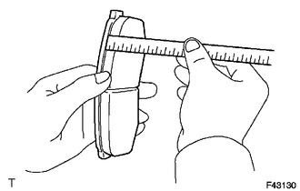
1. CHECK PAD LINING THICKNESS
|
(a) Using a ruler, measure the pad lining thickness. Standard thickness: 10.0 mm (0.394 in.) Minimum thickness: 1.0 mm (0.0394 in.) If the pad lining thickness is less than the minimum, replace the pad. |
|
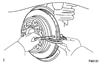
2. CHECK DISC THICKNESS
|
(a) Using a micrometer, measure the disc thickness. Standard thickness: 18.0 mm (0.709 in.) Minimum thickness: 16.0 mm (0.630 in.) If the disc thickness is less than the minimum, replace the disc. |
|
3. CHECK DISC RUNOUT
|
(a) Install the disc with the 6 hub nuts. Torque: for aluminum wheel : 103 N·m {1050 kgf·cm, 76 ft·lbf} for steel wheel : 112 N·m {1142 kgf·cm, 83 ft·lbf} |
|
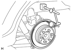
(b) Using a dial indicator, measure the disc runout 10 mm (0.394 in.) from the outer edge of the disc.
Maximum disc runout:
0.20 mm (0.00787 in.)
If the disc runout is more than the maximum, check the rear axle shaft (See page
.gif) ). If the rear axle shaft is normal, adjust the
). If the rear axle shaft is normal, adjust the
disc runout or grind the disc using an on-vehicle brake lathe.
4. ADJUST DISC RUNOUT
(a) Remove the 2 bolts and rear disc brake cylinder mounting from the backing plate.
(b) Remove the hub nuts and disc. Rotate the disc 1/5 of a turn from its original position on the hub and install the disc with the hub nuts.
Torque:
for aluminum wheel :
103 N·m {1050 kgf·cm, 76 ft·lbf}
for steel wheel :
112 N·m {1142 kgf·cm, 83 ft·lbf}
(c) Measure the disc runout. Make a note of the runout and the disc position on the hub.
(d) Repeat the 2 previous steps until the disc has been installed on the 3 remaining hub positions. If the minimum runout recorded above is less than 0.20 mm (0.00787 in.), install the disc in that position. If the minimum runout recorded above is more than 0.20 mm (0.00787 in.), replace the disc and repeat the "Check Disc Runout" procedure.
 Removal
REMOVAL
CAUTION / NOTICE / HINT
HINT:
Use the same procedure for the RH and LH sides.
The procedure listed below is for the LH side.
PROCEDURE
1. REMOVE REAR WHEEL
2. DRAIN BRA ...
 Reassembly
REASSEMBLY
PROCEDURE
1. INSTALL PISTON SEAL
(a) Apply a light layer of lithium soap base glycol grease to the entire
inner and outer circumference of a new piston seal.
Text in Il ...
Other materials about Toyota 4Runner:
Rear Combination Light Assembly
Components
COMPONENTS
ILLUSTRATION
Removal
REMOVAL
CAUTION / NOTICE / HINT
HINT:
Use the same procedure for both the RH and LH sides.
The procedure listed below is for the LH side.
PROCEDURE
1. REMOVE REAR COMBINATION LIGHT LEN ...
Short to GND in Immobiliser System Power Source Circuit (B278A)
DESCRIPTION
This DTC is stored when the engine switch power source supply line is open or
shorted.
DTC Code
DTC Detection Condition
Trouble Area
B278A
The engine switch power source supply line i ...

0.0083