Toyota 4Runner: Lost Communication with "Seat Control Module A" (U0208)
DESCRIPTION
|
DTC Code |
DTC Detection Condition |
Trouble Area |
|---|---|---|
|
U0208 |
There is no communication from the front power seat switch LH. |
|
HINT:
For vehicles with a seat position memory only.
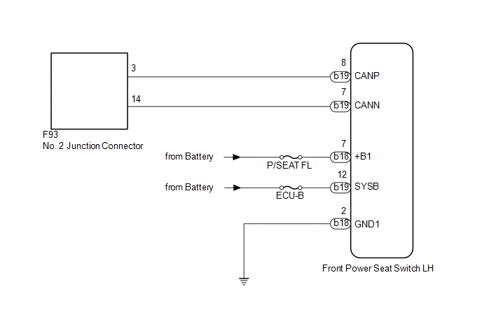
WIRING DIAGRAM
CAUTION / NOTICE / HINT
NOTICE:
Inspect the fuses for circuits related to this system before performing the following inspection procedure.
HINT:
Operating the ignition switch, any switches or any doors triggers related ECU and sensor communication with the CAN, which causes resistance variation.
PROCEDURE
|
1. |
DISCONNECT CABLE FROM NEGATIVE BATTERY TERMINAL |
(a) Disconnect the cable from the negative (-) battery terminal before measuring the resistances of the main wire and branch wire.
CAUTION:
Wait at least 90 seconds after disconnecting the cable from the negative (-) battery terminal to disable the SRS system.
NOTICE:
- When disconnecting the cable, some systems need to be initialized after
the cable is reconnected (See page
.gif) ).
).
|
.gif)
|
2. |
CHECK FOR OPEN IN CAN BUS WIRE (FRONT POWER SEAT SWITCH LH BRANCH WIRE) |
|
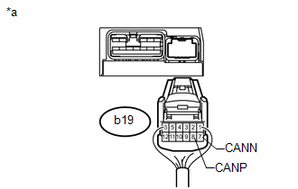
(a) Disconnect the b19 front power seat switch LH connector. |
|
(b) Measure the resistance according to the value(s) in the table below.
Standard Resistance:
|
Tester Connection |
Switch Condition |
Specified Condition |
|---|---|---|
|
b19-8 (CANP) - b19-7 (CANN) |
Ignition switch off |
54 to 69 Ω |
|
*a |
Rear view of wire harness connector (to Front Power Seat Switch LH) |
| NG | .gif) |
REPAIR OR REPLACE FRONT POWER SEAT SWITCH LH CAN BRANCH WIRE OR CONNECTOR (CANP, CANN) |
|
|
3. |
CHECK HARNESS AND CONNECTOR (FRONT POWER SEAT SWITCH LH - BATTERY AND BODY GROUND) |
|
(a) Connect the cable to the negative (-) battery terminal. NOTICE: When disconnecting the cable, some systems need to be initialized after
the cable is reconnected (See page |
|
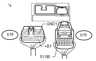
(b) Disconnect the b18 front power seat switch LH connector.
(c) Measure the resistance according to the value(s) in the table below.
Standard Resistance:
|
Tester Connection |
Condition |
Specified Condition |
|---|---|---|
|
b18-2 (GND1) - Body ground |
Always |
Below 1 Ω |
(d) Measure the voltage according to the value(s) in the table below.
Standard Voltage:
|
Tester Connection |
Condition |
Specified Condition |
|---|---|---|
|
b18-7 (+B1) - Body ground |
Always |
11 to 14 V |
|
b19-12 (SYSB) - Body ground |
Always |
11 to 14 V |
|
*a |
Rear view of wire harness connector (to Front Power Seat Switch LH) |
| OK | |
REPLACE FRONT POWER SEAT SWITCH LH |
| NG | |
REPAIR OR REPLACE HARNESS OR CONNECTOR |
 Lost Communication with ECM / PCM "A" (U0100)
DESCRIPTION
DTC Code
DTC Detection Condition
Trouble Area
U0100
There is no communication from the ECM.
Power source ...
 Lost Communication with A/C ECU (U0164)
DESCRIPTION
DTC Code
DTC Detection Condition
Trouble Area
U0164
There is no communication from the air conditioning amplifier assembly.
...
Other materials about Toyota 4Runner:
Disassembly
DISASSEMBLY
CAUTION / NOTICE / HINT
HINT:
Use the same procedure for the RH and LH sides.
The procedure listed below is for the LH side.
PROCEDURE
1. REMOVE FRONT FENDER OUTSIDE MOULDING PAD LH
(a) Remove the front fender outside moul ...
Removal
REMOVAL
PROCEDURE
1. DISCONNECT CABLE FROM NEGATIVE BATTERY TERMINAL
CAUTION:
Wait at least 90 seconds after disconnecting the cable from the negative (-)
battery terminal to disable the SRS system.
NOTICE:
When disconnecting the cable, some systems ne ...

0.0264