Toyota 4Runner: On-vehicle Inspection
ON-VEHICLE INSPECTION
PROCEDURE
1. INSPECT SEAT HEATER CONTROL SUB-ASSEMBLY LH
|
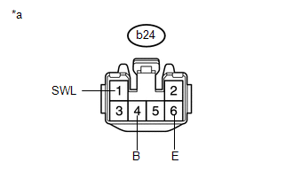
(a) Disconnect the b24 seat heater control sub-assembly LH connector. |
|
(b) Measure the resistance according to the value(s) in the table below.
Standard Resistance:
|
Tester Connection |
Condition |
Specified Condition |
|---|---|---|
|
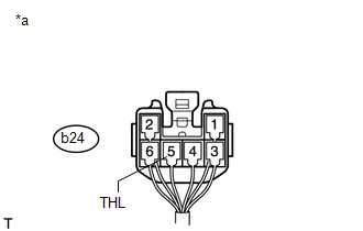
b24-6 (E) - Body ground |
Always |
Below 1 Ω |
(c) Measure the voltage according to the value(s) in the table below.
Standard Voltage:
|
Tester Connection |
Switch Condition |
Specified Condition |
|---|---|---|
|
b24-1 (SWL) - b24-6 (E) |
Engine switch on (IG) Refreshing seat switch LH side off |
Below 1 V |
|
Engine switch on (IG) Refreshing seat switch LH side on |
11 to 14 V |
|
|
b24-4 (B) - b24-6 (E) |
Engine switch off |
Below 1 V |
|
Engine switch on (IG) |
11 to 14 V |
|
*a |
Front view of wire harness connector (to Seat Heater Control Sub-assembly LH) |
If the result is not as specified, there may be a malfunction on the wire harness side.
(d) Connect the b24 seat heater control sub-assembly LH connector.
|
(e) Measure the voltage according to the value(s) in the table below. Standard Voltage:
If the result is not as specified, the seat heater control sub-assembly LH may have a malfunction. |
|
2. INSPECT SEAT HEATER CONTROL SUB-ASSEMBLY RH
|
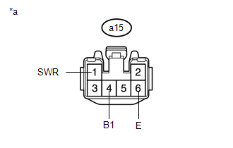
(a) Disconnect the a15 seat heater control sub-assembly LH connector. |
|
(b) Measure the resistance according to the value(s) in the table below.
Standard Resistance:
|
Tester Connection |
Condition |
Specified Condition |
|---|---|---|
|
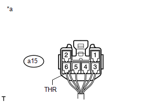
a15-6 (E) - Body ground |
Always |
Below 1 Ω |
(c) Measure the voltage according to the value(s) in the table below.
Standard Voltage:
|
Tester Connection |
Switch Condition |
Specified Condition |
|---|---|---|
|
a15-1 (SWR) - a15-6 (E) |
Engine switch on (IG) Refreshing seat switch RH side off |
Below 1 V |
|
Engine switch on (IG) Refreshing seat switch RH side on |
11 to 14 V |
|
|
a15-4 (B1) - a15-6 (E) |
Engine switch off |
Below 1 V |
|
Engine switch on (IG) |
11 to 14 V |
|
*a |
Front view of wire harness connector (to Seat Heater Control Sub-assembly RH) |
If the result is not as specified, there may be a malfunction on the wire harness side.
(d) Connect the a15 seat heater control sub-assembly LH connector.
|
(e) Measure the voltage according to the value(s) in the table below. Standard Voltage:
If the result is not as specified, the seat heater control sub-assembly LH may have a malfunction. |
|
 Problem Symptoms Table
PROBLEM SYMPTOMS TABLE
HINT:
Use the table below to help determine the cause of problem symptoms.
If multiple suspected areas are listed, the potential causes of the symptoms
are lis ...
 Terminals Of Ecu
TERMINALS OF ECU
1. AIR CONDITIONING AMPLIFIER
(a) Measure the voltage and resistance according to the value(s) in the table
below.
Terminal No. (Symbol)
Wiring Color
...
Other materials about Toyota 4Runner:
Manual (SOS) Switch Green Indicator Malfunction (B1571)
DESCRIPTION
This DTC is stored when the DCM (Telematics Transceiver) detects an open or short
in the manual (SOS) switch green indicator circuit of the manual (SOS) switch. The
manual (SOS) switch green indicator illuminates after the ignition switch is t ...
Removal
REMOVAL
CAUTION / NOTICE / HINT
HINT:
Use the same procedure for the RH and LH sides.
The procedure listed below is for the LH side.
PROCEDURE
1. DISCONNECT CABLE FROM NEGATIVE BATTERY TERMINAL
NOTICE:
When disconnecting the cable, som ...

0.0069