Toyota 4Runner: On-vehicle Inspection
ON-VEHICLE INSPECTION
PROCEDURE
1. REMOVE FRONT WHEEL
2. REMOVE DISC BRAKE CYLINDER ASSEMBLY LH
.gif)
3. REMOVE FRONT DISC
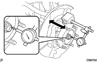
4. INSPECT FRONT AXLE HUB BEARING LOOSENESS
|
(a) Using a dial indicator, measure the looseness near the center of the axle hub. Maximum looseness: 0.05 mm (0.00197 in.) NOTICE: Make sure that the dial indicator is set at a right angle to the measurement surface. If the looseness is more than the maximum, replace the axle hub. |
|
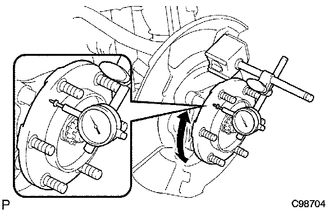
5. INSPECT FRONT AXLE HUB RUNOUT
|
(a) Using a dial indicator, measure the runout on the surface of the axle hub outside the hub bolts. Maximum runout: 0.08 mm (0.00315 in.) NOTICE: Make sure that the dial indicator is set at a right angle to the measurement surface. If the runout is more than the maximum, replace the axle hub. |
|
6. INSTALL FRONT DISC
7. INSTALL DISC BRAKE CYLINDER ASSEMBLY LH
8. INSTALL FRONT WHEEL
Torque:
for aluminum wheel :
103 N·m {1050 kgf·cm, 76 ft·lbf}
for steel wheel :
112 N·m {1142 kgf·cm, 83 ft·lbf}
 Components
COMPONENTS
ILLUSTRATION
...
 Removal
REMOVAL
CAUTION / NOTICE / HINT
HINT:
Use the same procedure for the RH and LH sides.
The procedure listed below is for the LH side.
PROCEDURE
1. REMOVE FRONT WHEEL
2. REMOVE D ...
Other materials about Toyota 4Runner:
Installation
INSTALLATION
CAUTION / NOTICE / HINT
CAUTION:
Wear protective gloves. Sharp areas on the parts may injure your hands.
HINT:
A bolt without a torque specification is shown in the standard bolt chart (See
page ).
PROCEDURE
1. INSTALL REAR SEAT CUSHION ...
Air Inlet Damper Control Servo Motor Circuit (B1442)
DESCRIPTION
The recirculation damper servo sub-assembly sends pulse signals to inform the
No. 1 air conditioning amplifier assembly of the damper position. The No. 1 air
conditioning amplifier assembly activates the motor (normal or reverse) based on
th ...

0.0071