Toyota 4Runner: Rear Combination Light Assembly
Components
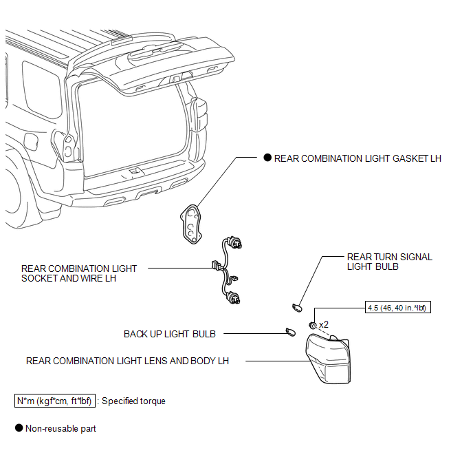
COMPONENTS
ILLUSTRATION
Removal
REMOVAL
CAUTION / NOTICE / HINT
HINT:
- Use the same procedure for both the RH and LH sides.
- The procedure listed below is for the LH side.
PROCEDURE
1. REMOVE REAR COMBINATION LIGHT LENS AND BODY LH
|
(a) Remove the cover. |
|
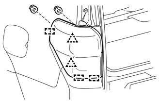
(b) Remove the 2 nuts.
(c) Detach the 2 clips and 3 guides to remove the rear combination light lens and body LH.
(d) Disconnect the connector.
Disassembly
DISASSEMBLY
CAUTION / NOTICE / HINT
HINT:
- Use the same procedure for both the RH and LH sides.
- The procedure listed below is for the LH side.
PROCEDURE
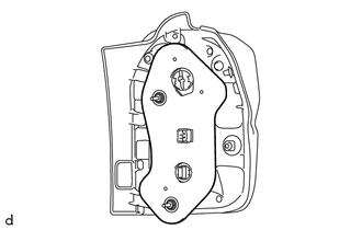
1. REMOVE REAR COMBINATION LIGHT GASKET LH
|
(a) Remove the rear combination light gasket LH. |
|
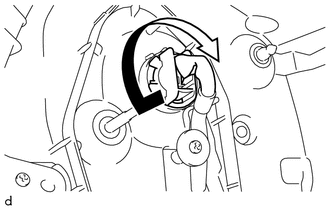
2. REMOVE REAR TURN SIGNAL LIGHT BULB
|
(a) Turn the socket in the direction indicated by the arrow to remove it. |
|

(b) Remove the rear turn signal light bulb.
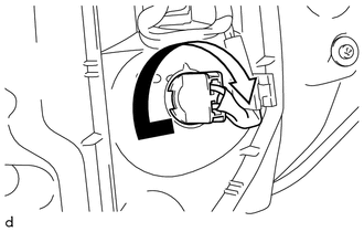
3. REMOVE BACK UP LIGHT BULB
|
(a) Turn the socket in the direction indicated by the arrow and remove it. |
|
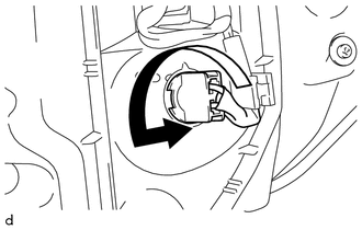
(b) Remove the back up light bulb.
4. REMOVE REAR COMBINATION LIGHT SOCKET AND WIRE LH
|
(a) Remove the screw. |
|
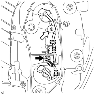
(b) Detach the 3 clamps.
(c) Disconnect the connector and remove the rear combination light socket and wire LH.
Reassembly
REASSEMBLY
CAUTION / NOTICE / HINT
HINT:
- Use the same procedure for both the RH and LH sides.
- The procedure listed below is for the LH side.
PROCEDURE
1. INSTALL REAR COMBINATION LIGHT SOCKET AND WIRE LH
|
(a) Connect the connector. |
|
.png)
(b) Attach the 3 clamps to install the rear combination light socket and wire LH.
(c) Install the screw.
2. INSTALL BACK UP LIGHT BULB
|
(a) Install the back up light bulb. |
|
(b) Turn the socket in the direction indicated by the arrow to install it.
3. INSTALL REAR TURN SIGNAL LIGHT BULB
|
(a) Install the rear turn signal light bulb. |
|
(b) Turn the socket in the direction indicated by the arrow to install it.
4. INSTALL REAR COMBINATION LIGHT GASKET LH
|
(a) Install a new rear combination light gasket LH. |
|
.png)
Installation
INSTALLATION
CAUTION / NOTICE / HINT
HINT:
- Use the same procedure for both the RH and LH sides.
- The procedure listed below is for the LH side.
PROCEDURE
1. INSTALL REAR COMBINATION LIGHT LENS AND BODY LH
(a) Attach the 2 clips and 3 guides to install the rear combination light lens and body LH.
(b) Install the 2 nuts.
Torque:
4.5 N·m {46 kgf·cm, 40 in·lbf}
(c) Connect the connector.
(d) Install the cover.
 Taillight Relay Circuit
DESCRIPTION
The main body ECU receives headlight dimmer switch information signals, and illuminates
the clearance lights, taillights and license plate lights.
WIRING DIAGRAM
CAUTION / NOTICE / ...
 Relay
Relay
On-vehicle Inspection
ON-VEHICLE INSPECTION
PROCEDURE
1. REMOVE HEADLIGHT RELAY
(a) Remove the headlight relay from the engine room relay box.
...
Other materials about Toyota 4Runner:
Using the storage features
List of storage features
1. Auxiliary boxes
2. Glove box
3. Bottle holders
4. Tissue pocket
5. Cup holders
6. Pen holder
7. Console box
8. Coin holder
CAUTION
Items that should not be left in the storage spaces
Do not leave glasses, lighte ...
Operation Check
OPERATION CHECK
1. NOTICES WHEN CHECKING
(a) Wireless door lock/unlock function:
The wireless door lock control function operates only when the following conditions
are met:
The engine switch is off.
All the doors are closed.
HINT:
The u ...

0.0149