Toyota 4Runner: Taillight Relay Circuit
DESCRIPTION
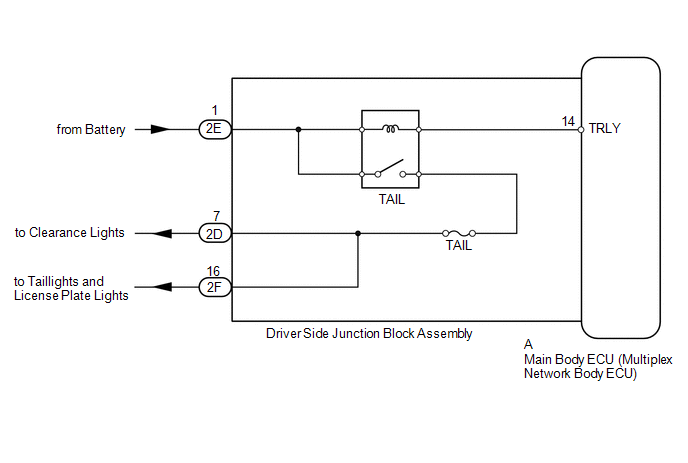
The main body ECU receives headlight dimmer switch information signals, and illuminates the clearance lights, taillights and license plate lights.
WIRING DIAGRAM
CAUTION / NOTICE / HINT
NOTICE:
Inspect the fuses and bulbs for circuits related to this system before performing the following inspection procedure.
PROCEDURE
|
1. |
PERFORM ACTIVE TEST USING TECHSTREAM (TAILLIGHT RELAY) |
(a) Using the Techstream, perform the Active Test (See page
.gif) ).
).
Main Body
|
Tester Display |
Test Part |
Control Range |
Diagnostic Note |
|---|---|---|---|
|
Taillight Relay |
Taillight relay |
ON/OFF |
- |
OK:
Taillight relay operates (taillights illuminate).
| OK | .gif) |
PROCEED TO NEXT SUSPECTED AREA SHOWN IN PROBLEM SYMPTOMS TABLE |
|
.gif)
|
2. |
CHECK HARNESS AND CONNECTOR (BATTERY - MAIN BODY ECU) |
|
(a) Remove the main body ECU (See page
|
|
(b) Measure the voltage according to the value(s) in the table below.
Standard Voltage:
|
Tester Connection |
Condition |
Specified Condition |
|---|---|---|
|
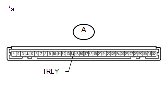
A-14 (TRLY) - Body ground |
Always |
11 to 14 V |
|
*a |
Front view of wire harness connector (to Main Body ECU) |
| OK | |
PROCEED TO NEXT SUSPECTED AREA SHOWN IN PROBLEM SYMPTOMS TABLE |
| NG | |
REPAIR OR REPLACE HARNESS OR CONNECTOR |
 Front Fog Light Circuit
DESCRIPTION
The main body ECU receives headlight dimmer switch information signals, and illuminates
the front fog light.
WIRING DIAGRAM
CAUTION / NOTICE / HINT
NOTICE:
Inspect the fuses and b ...
 Rear Combination Light Assembly
Components
COMPONENTS
ILLUSTRATION
Removal
REMOVAL
CAUTION / NOTICE / HINT
HINT:
Use the same procedure for both the RH and LH sides.
The procedure listed below is for the LH ...
Other materials about Toyota 4Runner:
Installation
INSTALLATION
PROCEDURE
1. INSTALL STABILIZER CONTROL WITH ACCUMULATOR HOUSING ASSEMBLY
(a) Install the stabilizer control with accumulator housing with the 3 bolts.
Torque:
29 N·m {296 kgf·cm, 21 ft·lbf}
(b) Connect the connector, and then attach the ...
Installation
INSTALLATION
PROCEDURE
1. INSTALL SLIDING ROOF HOUSING SUB-ASSEMBLY
(a) Temporarily install the housing with the 8 bolts (vehicle body side) and
8 nuts.
(b) Tighten the 8 nuts in alphabetical order.
Torque:
5.5 N·m {56 kgf·cm, 49 in·lbf}
(c) Tight ...

0.0261