Toyota 4Runner: Rear Power Window RH Auto Up / Down Function does not Operate with Rear Power Window Switch RH
DESCRIPTION
If the auto up/down function does not operate, the cause may be one or more of the following:
- The ECU in the power window regulator motor determines that the power window regulator motor has not been initialized.
- The rear power window regulator switch has a malfunction.
- The Hall IC in the power window regulator motor has a malfunction.
- There is an open or short in the wiring between the rear power window regulator switch and power window regulator motor.
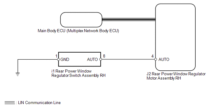
WIRING DIAGRAM
CAUTION / NOTICE / HINT
HINT:
Since the power window control system has functions that use LIN communication, first confirm that there is no malfunction in the communication system by inspecting the LIN communication functions in accordance with the "How to Proceed with Troubleshooting" procedures. Then, conduct the following inspection procedure.
PROCEDURE
|
1. |
CHECK FOR DTC |
(a) Clear the DTCs (See page .gif) ).
).
(b) Check for DTCs (See page ).
Result:
|
Result |
Proceed to |
|---|---|
|
DTC is not output |
A |
|
DTC B2311 is output |
B |
|
DTC B2312 is output |
C |
|
DTC B2313 is output |
D |
| B | .gif) |
GO TO DTC B2311 |
| C | |
GO TO DTC B2312 |
| D | |
GO TO DTC B2313 |
|
.gif)
|
2. |
CHECK MANUAL UP/DOWN FUNCTION (REAR POWER WINDOW REGULATOR SWITCH ASSEMBLY RH) |
(a) Check that the manual up/down function using the rear power window regulator
switch can operate the rear power window regulator motor (See page
).
OK:
Manual up/down function operates.
| NG | |
GO TO "Rear Power Window RH does not Operate with Rear Power Window Switch RH" |
|
|
3. |
READ VALUE USING TECHSTREAM (REAR POWER WINDOW REGULATOR SWITCH) |
(a) Use the Data List to check if the power window regulator is functioning properly
(See page ).
RR-Door Motor
|
Tester Display |
Measurement Item/Range |
Normal Condition |
Diagnostic Note |
|---|---|---|---|
|
RR Door P/W Auto SW |
Rear power window RH auto up/down signal / ON or OFF |
ON: Rear power window RH auto up/down switch operated OFF: Rear power window RH switch not operated |
- |
OK:
On tester screen, item changes between ON and OFF according to above chart.
| OK | |
REPLACE REAR POWER WINDOW REGULATOR MOTOR ASSEMBLY RH |
|
|
4. |
INSPECT REAR POWER WINDOW REGULATOR SWITCH ASSEMBLY RH |
|
(a) Remove the rear power window regulator switch (See page
|
|
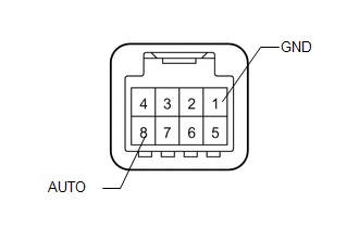
(b) Measure the resistance according to the value(s) in the table below.
Standard Resistance:
|
Tester Connection |
Switch Condition |
Specified Condition |
|---|---|---|
|
8 (AUTO) - 1 (GND) |
Auto up/down operation |
Below 1 Ω |
|
8 (AUTO) - 1 (GND) |
Not operated |
10 kΩ or higher |
| NG | |
REPLACE REAR POWER WINDOW REGULATOR SWITCH ASSEMBLY RH |
|
|
5. |
CHECK HARNESS AND CONNECTOR (REAR POWER WINDOW REGULATOR SWITCH RH - REAR POWER WINDOW REGULATOR MOTOR RH AND BODY GROUND) |
(a) Disconnect the i1 rear power window regulator switch connector.
(b) Disconnect the J2 power window regulator motor connector.
(c) Measure the resistance according to the value(s) in the table below.
Standard Resistance:
|
Tester Connection |
Condition |
Specified Condition |
|---|---|---|
|
i1-8 (AUTO) - J2-4 (AUTO) |
Always |
Below 1 Ω |
|
i1-1 (GND) - Body ground |
Always |
Below 1 Ω |
|
i1-8 (AUTO) - Body ground |
Always |
10 kΩ or higher |
| OK | |
REPLACE REAR POWER WINDOW REGULATOR MOTOR ASSEMBLY RH |
| NG | |
REPAIR OR REPLACE HARNESS OR CONNECTOR |
 Rear Power Window LH Auto Up / Down Function does not Operate with Rear Power
Window Switch LH
Rear Power Window LH Auto Up / Down Function does not Operate with Rear Power
Window Switch LH
DESCRIPTION
If the auto up/down function does not operate, the cause may be one or more of
the following:
The ECU in the power window regulator motor determines that the power
window re ...
 All Power Windows do not Operate with Driver Side Door Key Cylinder or Wireless
Transmitter
All Power Windows do not Operate with Driver Side Door Key Cylinder or Wireless
Transmitter
DESCRIPTION
When a key switch is pushed: 1) the door control receiver receives the
key signal; 2) the door control receiver sends a signal to the certification
ECU; 3) the main body EC ...
Other materials about Toyota 4Runner:
Back Sonar Sensor RH Circuit
DESCRIPTION
The ultrasonic sensor sends and receives ultrasonic waves. Based on the received
wave, the sensor calculates the approximate distance between the vehicle and the
obstacle, and sends the distance value as a signal to the clearance warning ECU
...
Registration
REGISTRATION
PROCEDURE
1. DESCRIPTION OF CODE REGISTRATION
HINT:
Recognition code registration is necessary when replacing door control
transmitter or door control receiver.
Add mode is used to register new recognition codes while still ret ...
0.0129