Toyota 4Runner: Reassembly
REASSEMBLY
PROCEDURE
1. INSTALL FRONT UPPER BALL JOINT DUST COVER LH
|
(a) Pack the upper arm ball joint with MP grease. Grease capacity: 8.0 g (0.282 oz.) Text in Illustration
|
|
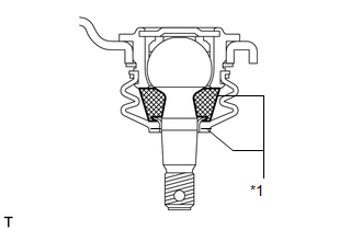
(b) Apply MP grease to the locations shown in the illustration.
NOTICE:
Do not apply MP grease to the tapered or threaded parts of the ball joint.
(c) Install the dust cover to the upper arm.
|
(d) Using a snap ring expander, install the dust cover set ring. NOTICE: Make sure the set ring is securely installed in the groove. |
|
.png)
2. INSTALL FRONT SUSPENSION UPPER ARM BUSH LH
|
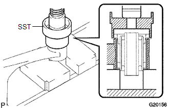
(a) Using SST and a press, press in a new bush. SST: 09710-26011 09710-05061 HINT: Press in the rear side bush using the same procedure as for the front side. |
|
 Inspection
INSPECTION
PROCEDURE
1. INSPECT FRONT SUSPENSION UPPER ARM ASSEMBLY LH
(a) As shown in the illustration, flip the ball joint stud back and forth
5 times before installing the nut.
...
 Installation
INSTALLATION
CAUTION / NOTICE / HINT
HINT:
Use the same procedure for the RH and LH sides.
The procedure listed below is for the LH side.
A bolt without a torque specification is sh ...
Other materials about Toyota 4Runner:
Combination Meter
Components
COMPONENTS
ILLUSTRATION
ILLUSTRATION
ILLUSTRATION
Removal
REMOVAL
PROCEDURE
1. DISCONNECT CABLE FROM NEGATIVE BATTERY TERMINAL
CAUTION:
Wait at least 90 seconds after disconnecting the cable from the negative (-)
battery termin ...
Installation
INSTALLATION
CAUTION / NOTICE / HINT
HINT:
A bolt without a torque specification is shown in the standard bolt chart (See
page ).
PROCEDURE
1. INSTALL POWER MANAGEMENT CONTROL ECU
(a) Attach the 2 claws to install the power management control ECU.
2. ...

0.0065