Toyota 4Runner: Reassembly
REASSEMBLY
PROCEDURE
1. INSTALL SHIFT SOLENOID VALVE S2
|
(a) Coat a new O-ring with ATF and install it to the solenoid valve. Text in Illustration
|
|
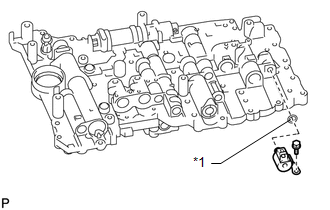
(b) Install the solenoid valve with the bolt.
Torque:
10 N·m {102 kgf·cm, 7 ft·lbf}
2. INSTALL SHIFT SOLENOID VALVE S1
.png)
(a) Install the solenoid valve with the bolt.
Torque:
6.4 N·m {65 kgf·cm, 57 in·lbf}
3. INSTALL SHIFT SOLENOID VALVE SL1
.png)
4. INSTALL SHIFT SOLENOID VALVE SLT
|
(a) Install the solenoid valve. |
|
.png)
(b) Install the 2 straight pins and solenoid lock plate with the bolt.
Torque:
6.4 N·m {65 kgf·cm, 57 in·lbf}
5. INSTALL SHIFT SOLENOID VALVE SL2
.png)
6. INSTALL SHIFT SOLENOID VALVE SLU
|
(a) Install the solenoid valve. |
|
.png)
(b) Install 2 straight pins and solenoid lock plate with the bolt.
Torque:
6.4 N·m {65 kgf·cm, 57 in·lbf}
7. INSTALL SHIFT SOLENOID VALVE SR
|
(a) Install the solenoid valve with the 2 bolts. Torque: 6.4 N·m {65 kgf·cm, 57 in·lbf} |
|
.png)
 Installation
INSTALLATION
PROCEDURE
1. INSTALL TRANSMISSION VALVE BODY ASSEMBLY
(a) Install the spring and check ball body.
(b) Insert the pin of the manual valve into the hole of the manual valve
...

Other materials about Toyota 4Runner:
System Diagram
SYSTEM DIAGRAM
Terminal No. (Symbol)
Wire Harness Side
F14
1 (CANH)
CAN communication line (V Bus)
2 (CANL)
CAN communication line (V Bus)
3 (MSS ...
Yaw Rate Sensor Malfunction (C1436)
DESCRIPTION
Refer to DTC C1419 and C1435 (See page ).
DTC Code
DTC Detection Condition
Trouble Area
C1436
Either condition is met:
With the vehicle stationary, the yaw rate and accel ...

0.0076