Toyota 4Runner: Short in Sensor with Motor Power Supply Circuit (B2658)
DESCRIPTION
This DTC is stored when a power seat motor operates (a position control sensor is being supplied with power) and the power supply voltage does not rise to the specified value.
|
DTC Code |
DTC Detection Condition |
Trouble Area |
|---|---|---|
|
B2658 |
A problem with the voltage supplied to the position control sensor. |
|
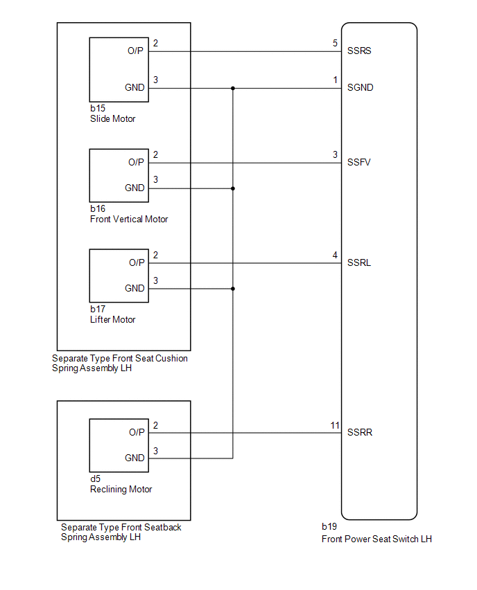
WIRING DIAGRAM
PROCEDURE
|
1. |
CHECK FOR DTC |
(a) Clear the DTCs (See page .gif) ).
).
(b) Check for DTCs (See page ).
OK:
DTC B2658 is not output.
| OK | .gif) |
USE SIMULATION METHOD TO CHECK |
|
.gif)
|
2. |
CHECK HARNESS AND CONNECTOR (FRONT POWER SEAT SWITCH LH - SLIDE MOTOR) |
(a) Disconnect the b19 front power seat switch LH connector.
(b) Disconnect the b15 slide motor connector.
(c) Measure the resistance according to the value(s) in the table below.
Standard Resistance:
|
Tester Connection |
Condition |
Specified Condition |
|---|---|---|
|
b19-5 (SSRS) - b15-2 (O/P) |
Always |
Below 1 Ω |
|
b19-1 (SGND) - b15-3 (GND) |
Always |
Below 1 Ω |
|
b19-5 (SSRS) - b19-1 (SGND) |
Always |
10 kΩ or higher |
|
b19-5 (SSRS) - Body ground |
Always |
10 kΩ or higher |
|
b19-1 (SGND) - Body ground |
Always |
10 kΩ or higher |
| NG | |
REPAIR OR REPLACE HARNESS OR CONNECTOR |
|
|
3. |
CHECK FRONT POWER SEAT SWITCH LH (SLIDE MOTOR CIRCUIT) |
|
(a) Connect the b19 front power seat switch LH connector. |
|
(b) Measure the voltage according to the value(s) in the table below.
Standard Voltage:
|
Tester Connection |
Switch Condition |
Specified Condition |
|---|---|---|
|
b15-2 (O/P) - b15-3 (GND) |
Sliding switch on |
4.8 to 5.1 V |
|
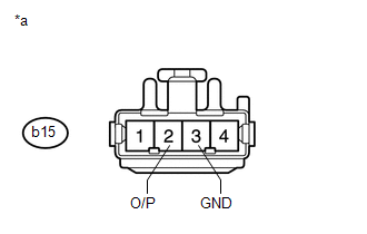
*a |
Front view of wire harness connector (to Separate Type Front Seat Cushion Spring Assembly LH [Slide Motor]) |
| NG | |
REPLACE FRONT POWER SEAT SWITCH LH |
|
|
4. |
CHECK HARNESS AND CONNECTOR (FRONT POWER SEAT SWITCH LH - FRONT VERTICAL MOTOR) |
(a) Disconnect the b19 front power seat switch LH connector.
(b) Disconnect the b16 front vertical motor connector.
(c) Measure the resistance according to the value(s) in the table below.
Standard Resistance:
|
Tester Connection |
Condition |
Specified Condition |
|---|---|---|
|
b19-3 (SSFV) - b16-2 (O/P) |
Always |
Below 1 Ω |
|
b19-1 (SGND) - b16-3 (GND) |
Always |
Below 1 Ω |
|
b19-3 (SSFV) - b19-1 (SGND) |
Always |
10 kΩ or higher |
|
b19-3 (SSFV) - Body ground |
Always |
10 kΩ or higher |
|
b19-1 (SGND) - Body ground |
Always |
10 kΩ or higher |
| NG | |
REPAIR OR REPLACE HARNESS OR CONNECTOR |
|
|
5. |
CHECK FRONT POWER SEAT SWITCH LH (FRONT VERTICAL MOTOR CIRCUIT) |
|
(a) Connect the b19 front power seat switch LH connector. |
|
(b) Measure the voltage according to the value(s) in the table below.
Standard Voltage:
|
Tester Connection |
Switch Condition |
Specified Condition |
|---|---|---|
|
b16-2 (O/P) - b16-3 (GND) |
Front vertical switch on |
4.8 to 5.1 V |
|
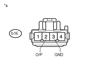
*a |
Front view of wire harness connector (to Separate Type Front Seat Cushion Spring Assembly LH [Front Vertical Motor]) |
| NG | |
REPLACE FRONT POWER SEAT SWITCH LH |
|
|
6. |
CHECK HARNESS AND CONNECTOR (FRONT POWER SEAT SWITCH LH - LIFTER MOTOR) |
(a) Disconnect the b19 front power seat switch LH connector.
(b) Disconnect the b17 lifter motor connector.
(c) Measure the resistance according to the value(s) in the table below.
Standard Resistance:
|
Tester Connection |
Condition |
Specified Condition |
|---|---|---|
|
b19-4 (SSRL) - b17-2 (O/P) |
Always |
Below 1 Ω |
|
b19-1 (SGND) - b17-3 (GND) |
Always |
Below 1 Ω |
|
b19-4 (SSRL) - b19-1 (SGND) |
Always |
10 kΩ or higher |
|
b19-4 (SSRL) - Body ground |
Always |
10 kΩ or higher |
|
b19-1 (SGND) - Body ground |
Always |
10 kΩ or higher |
| NG | |
REPAIR OR REPLACE HARNESS OR CONNECTOR |
|
|
7. |
CHECK FRONT POWER SEAT SWITCH LH (LIFTER MOTOR CIRCUIT) |
|
(a) Connect the b19 front power seat switch LH connector. |
|
(b) Measure the voltage according to the value(s) in the table below.
Standard Voltage:
|
Tester Connection |
Switch Condition |
Specified Condition |
|---|---|---|
|
b17-2 (O/P) - b17-3 (GND) |
Lifter switch on |
4.8 to 5.1 V |
|
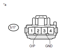
*a |
Front view of wire harness connector (to Separate Type Front Seat Cushion Spring Assembly LH [Lifter Motor]) |
| NG | |
REPLACE FRONT POWER SEAT SWITCH LH |
|
|
8. |
CHECK HARNESS AND CONNECTOR (FRONT POWER SEAT SWITCH LH - RECLINING MOTOR) |
(a) Disconnect the b19 front power seat switch LH connector.
(b) Disconnect the d5 reclining motor connector.
(c) Measure the resistance according to the value(s) in the table below.
Standard Resistance:
|
Tester Connection |
Condition |
Specified Condition |
|---|---|---|
|
b19-11 (SSRR) - d5-2 (O/P) |
Always |
Below 1 Ω |
|
b19-1 (SGND) - d5-3 (GND) |
Always |
Below 1 Ω |
|
b19-11 (SSRR) - b19-1 (SGND) |
Always |
10 kΩ or higher |
|
b19-11 (SSRR) - Body ground |
Always |
10 kΩ or higher |
|
b19-1 (SGND) - Body ground |
Always |
10 kΩ or higher |
| NG | |
REPAIR OR REPLACE HARNESS OR CONNECTOR |
|
|
9. |
CHECK FRONT POWER SEAT SWITCH LH (RECLINING MOTOR CIRCUIT) |
|
(a) Connect the b19 front power seat switch LH connector. |
|
(b) Measure the voltage according to the value(s) in the table below.
Standard Voltage:
|
Tester Connection |
Switch Condition |
Specified Condition |
|---|---|---|
|
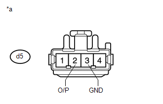
d5-2 (O/P) - d5-3 (GND) |
Reclining switch on |
4.8 to 5.1 V |
|
*a |
Front view of wire harness connector (to Separate Type Front Seatback Spring Assembly LH [Reclining Motor]) |
| NG | |
REPLACE FRONT POWER SEAT SWITCH LH |
|
|
10. |
CHECK SEPARATE TYPE FRONT SEAT CUSHION SPRING ASSEMBLY LH |
(a) Temporarily replace the separate type front seat cushion spring with a new
or normally functioning one (See page ).
(b) Clear the DTCs (See page ).
(c) Check for DTCs (See page ).
OK:
DTC B2658 is not output.
| OK | |
END (SEPARATE TYPE FRONT SEAT CUSHION SPRING ASSEMBLY LH IS DEFECTIVE) |
|
|
11. |
CHECK SEPARATE TYPE FRONT SEATBACK SPRING ASSEMBLY LH |
(a) Temporarily replace the separate type front seatback spring with a new or
normally functioning one (See page ).
(b) Clear the DTCs (See page ).
(c) Check for DTCs (See page ).
OK:
DTC B2658 is not output.
| OK | |
END (SEPARATE TYPE FRONT SEATBACK SPRING ASSEMBLY LH IS DEFECTIVE) |
| NG | |
REPLACE FRONT POWER SEAT SWITCH LH |
 Lifter Sensor Malfunction (B2653)
DESCRIPTION
When the front power seat switch LH does not receive a sensor signal despite
upward or downward movement of the seat by power seat motor operation, this DTC
is stored.
DTC ...
 Reclining Sensor Malfunction (B2651)
DESCRIPTION
When the front power seat switch LH does not receive a sensor signal despite
forward or backward movement of the seatback by power seat motor operation, this
DTC is stored.
...
Other materials about Toyota 4Runner:
Reverse Signal Circuit
DESCRIPTION
The navigation receiver assembly receives a reverse signal from the park/neutral
position switch assembly.
WIRING DIAGRAM
CAUTION / NOTICE / HINT
NOTICE:
After replacing the navigation receiver assembly of vehicles subscribed
t ...
Installation
INSTALLATION
PROCEDURE
1. INSTALL FRONT DRIVE SHAFT ASSEMBLY
(a) Coat the spline of the inboard joint shaft assembly with ATF.
(b) Align the shaft splines and install the drive shaft with a brass bar and
hammer.
NOTICE:
Set the snap ring with ...

0.0135