Toyota 4Runner: Lifter Sensor Malfunction (B2653)
DESCRIPTION
When the front power seat switch LH does not receive a sensor signal despite upward or downward movement of the seat by power seat motor operation, this DTC is stored.
|
DTC Code |
DTC Detection Condition |
Trouble Area |
|---|---|---|
|
B2653 |
The upward and downward lock detection position of the sensor is the same. |
|
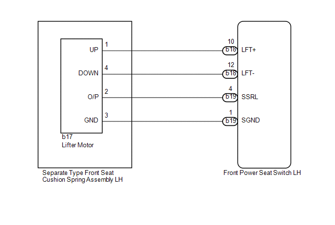
WIRING DIAGRAM
PROCEDURE
|
1. |
PERFORM ACTIVE TEST USING TECHSTREAM (POWER SEAT MOTOR FUNCTION) |
(a) Select the Active Test, use the Techstream to generate a control command,
and then check the power seat motor function (See page
.gif) ).
).
|
Tester Display |
Test Part |
Control Range |
Diagnostic Note |
|---|---|---|---|
|
Lifter Operation |
Seat lifter operation |
Up / OFF / Down |
- |
OK:
Motor operates normally.
| NG | .gif) |
GO TO STEP 5 |
|
.gif)
|
2. |
CHECK FRONT POWER SEAT SWITCH LH (LIFTER MOTOR CIRCUIT) |
|
(a) Disconnect the b17 lifter motor connector. |
|
(b) Measure the voltage according to the value(s) in the table below.
Standard Voltage:
|
Tester Connection |
Switch Condition |
Specified Condition |
|---|---|---|
|
b17-2 (O/P) - b17-3 (GND) |
Lifter switch on |
4.8 to 5.1 V |
|
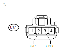
*a |
Front view of wire harness connector (to Separate Type Front Seat Cushion Spring Assembly LH [Lifter Motor]) |
| NG | |
GO TO STEP 4 |
|
|
3. |
CHECK SEPARATE TYPE FRONT SEAT CUSHION SPRING ASSEMBLY LH (LIFTER MOTOR) |
|
(a) Connect the b17 lifter motor connector. |
|
(b) Measure the voltage according to the value(s) in the table below.
Standard Voltage:
|
Tester Connection |
Switch Condition |
Specified Condition |
|---|---|---|
|
b17-2 (O/P) - Body ground |
Lifter switch on |
4.5 to 4.8 V |
|
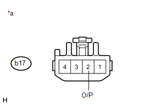
*a |
Component with harness connected (Separate Type Front Seat Cushion Spring Assembly LH [Lifter Motor]) |
| OK | |
REPLACE FRONT POWER SEAT SWITCH LH |
| NG | |
REPLACE SEPARATE TYPE FRONT SEAT CUSHION SPRING ASSEMBLY LH (LIFTER MOTOR) |
|
4. |
CHECK HARNESS AND CONNECTOR (FRONT POWER SEAT SWITCH - LIFTER MOTOR) |
(a) Disconnect the b19 front power seat switch LH connector.
(b) Disconnect the b17 lifter motor connector.
(c) Measure the resistance according to the value(s) in the table below.
Standard Resistance:
|
Tester Connection |
Condition |
Specified Condition |
|---|---|---|
|
b19-4 (SSRL) - b17-2 (O/P) |
Always |
Below 1 Ω |
|
b19-1 (SGND) - b17-3 (GND) |
Always |
Below 1 Ω |
|
b19-4 (SSRL) - Body ground |
Always |
10 kΩ or higher |
|
b19-1 (SGND) - Body ground |
Always |
10 kΩ or higher |
| OK | |
REPLACE FRONT POWER SEAT SWITCH LH |
| NG | |
REPAIR OR REPLACE HARNESS OR CONNECTOR |
|
5. |
INSPECT SEPARATE TYPE FRONT SEAT CUSHION SPRING ASSEMBLY LH (LIFTER MOTOR) |
|
(a) Remove the separate type front seat cushion spring assembly LH (lifter
motor) (See page |
|
(b) Disconnect the b17 lifter motor connector.
(c) Check if the seat cushion spring moves smoothly when the battery is connected to the lifter motor connector terminals.
OK:
|
Measurement Condition |
Operational Direction |
|---|---|
|
Battery positive (+) → 1 (UP) Battery negative (-) → 4 (DOWN) |
Seat cushion spring moves upward |
|
Battery positive (+) → 4 (DOWN) Battery negative (-) → 1 (UP) |
Seat cushion spring moves downward |
|
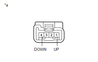
*a |
Component without harness connected (Separate Type Front Seat Cushion Spring Assembly LH [Lifter Motor]) |
| NG | |
REPLACE SEPARATE TYPE FRONT SEAT CUSHION SPRING ASSEMBLY LH (LIFTER MOTOR) |
|
|
6. |
CHECK HARNESS AND CONNECTOR (FRONT POWER SEAT SWITCH LH - LIFTER MOTOR) |
(a) Disconnect the b18 front power seat switch LH connector.
(b) Disconnect the b17 lifter motor connector.
(c) Measure the resistance according to the value(s) in the table below.
Standard Resistance:
|
Tester Connection |
Condition |
Specified Condition |
|---|---|---|
|
b18-10 (LFT+) - b17-1 (UP) |
Always |
Below 1 Ω |
|
b18-12 (LFT-) - b17-4 (DOWN) |
Always |
Below 1 Ω |
|
b18-10 (LFT+) - Body ground |
Always |
10 kΩ or higher |
|
b18-12 (LFT-) - Body ground |
Always |
10 kΩ or higher |
| OK | |
REPLACE FRONT POWER SEAT SWITCH LH |
| NG | |
REPAIR OR REPLACE HARNESS OR CONNECTOR |
 Diagnostic Trouble Code Chart
DIAGNOSTIC TROUBLE CODE CHART
Front Power Seat Control System
DTC Code
Detection Item
See page
B2650
Slide Sensor Malfunction
...
 Short in Sensor with Motor Power Supply Circuit (B2658)
DESCRIPTION
This DTC is stored when a power seat motor operates (a position control sensor
is being supplied with power) and the power supply voltage does not rise to the
specified value.
...
Other materials about Toyota 4Runner:
Making a phone call
Making a phone call
• Dialing by inputting a number “Dial by Number”
• Dialing by inputting a name “Dial by Name (Dial by name)” •
Speed dialing
• Dialing a number stored in the outgoing history memory “Redial”
• Dialing a numb ...
Reassembly
REASSEMBLY
PROCEDURE
1. INSTALL FOG LIGHT ASSEMBLY LH
2. INSTALL FOG LIGHT ASSEMBLY RH
HINT:
Use the same procedure as for the LH side.
3. INSTALL FRONT BUMPER MOULDING SUB-ASSEMBLY
(a) Attach the 4 claws and 12 guides to install the front bumper mou ...

0.0073