Toyota 4Runner: Short to GND in Motor LH Circuit (21,23)
DESCRIPTION
When there is a short to GND in the side auto step motor circuit, the side auto step controller ECU assembly does not operate the automatic running board.
|
DTC No. |
Detection Condition |
Trouble Area |
|---|---|---|
|
21 |
Short to GND in the circuit on the stowing or deploying side of the side auto step motor LH. |
|
|
23 |
Short to GND in the circuit on the stowing or deploying side of the side auto step motor RH. |
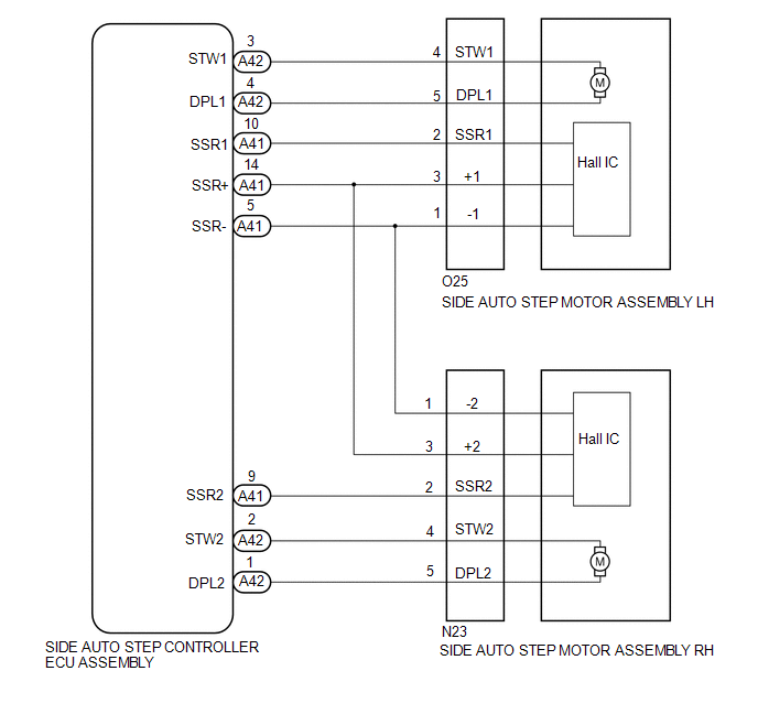
WIRING DIAGRAM
PROCEDURE
|
1. |
INSPECT SIDE AUTO STEP MOTOR ASSEMBLY |
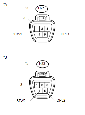
(a) Disconnect the O25*1 or N23*2 side auto step motor assembly connector.
- *1: for LH
- *2: for RH
|
(b) Measure the resistance according to the value(s) in the table below. Standard Resistance: for LH
for RH
|
|
| NG | .gif) |
REPLACE SIDE AUTO STEP MOTOR ASSEMBLY |
|
.gif)
|
2. |
CHECK HARNESS AND CONNECTOR (SIDE AUTO STEP MOTOR - SIDE AUTO STEP CONTROLLER ECU) |
(a) Disconnect the A42 side auto step controller ECU assembly connector.
(b) Measure the resistance according to the value(s) in the table below.
Standard Resistance:
for LH
|
Tester Connection |
Condition |
Specified Condition |
|---|---|---|
|
A42-3 (STW1) - Body ground |
Always |
10 kΩ or higher |
|
A42-4 (DPL1) - Body ground |
Always |
10 kΩ or higher |
for RH
|
Tester Connection |
Condition |
Specified Condition |
|---|---|---|
|
A42-2 (STW2) - Body ground |
Always |
10 kΩ or higher |
|
A42-1 (DPL1) - Body ground |
Always |
10 kΩ or higher |
| OK | |
REPLACE SIDE AUTO STEP CONTROLLER ECU ASSEMBLY |
| NG | |
REPAIR OR REPLACE HARNESS OR CONNECTOR |
 Short in Motor LH (11,12)
DESCRIPTION
When there is a short in the side auto step motor circuit, the side auto step
controller ECU assembly halts the operation of the automatic running board.
DTC No.
...
 Side Auto Step ECU Power Source Circuit
WIRING DIAGRAM
CAUTION / NOTICE / HINT
NOTICE:
Inspect the fuses for circuits related to this system before performing the following
inspection procedure.
PROCEDURE
1.
...
Other materials about Toyota 4Runner:
LIN Communication Master Malfunction (B2287,B278C)
DESCRIPTION
DTC B2287 is stored when there is an open or short circuit or an ECU
communication malfunction between the power management control ECU and certification
ECU.
DTC B278C is stored when LIN communication between the certification ...
VFC Solenoid Circuit (C15F0)
DESCRIPTION
This circuit supplies electric power to the power steering solenoid valve.
The power steering ECU assembly controls the output current to the power steering
solenoid valve in accordance with the steering angle signal, steering zero point
memo ...

0.0176