Toyota 4Runner: System Description
SYSTEM DESCRIPTION
1. DESCRIPTION OF SYSTEM
(a) When the tire pressure warning system detects that the tire pressure of a tire is below the threshold, it illuminates the tire pressure warning light to warn the driver.
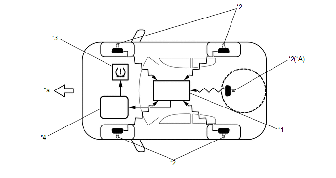
(b) The tire pressure warning antenna and receiver receives the transmitter ID, temperature and tire pressure information from the tire pressure warning valve and transmitters shown in the following illustration. This information is used to determine when the pressure in one of the tires has dropped.
 Text in Illustration
|
*A |
w/ Spare Tire Pressure Warning Valve and Transmitter |
- |
- |
|
*1 |
Tire Pressure Warning Antenna and Receiver |
*2 |
Tire Pressure Warning Valve and Transmitter |
|
*3 |
Combination Meter Assembly - Tire Pressure Warning Light |
*4 |
Tire Pressure Warning ECU |
|
*a |
Front |
- |
- |
2. DESCRIPTION OF REGISTRATION
(a) When tires and wheels are replaced, always make sure that each transmitter ID is correctly registered.
(b) When one or more tire pressure warning valve and transmitters or the tire pressure warning ECU is replaced, the transmitter IDs for all of the tire pressure warning valve and transmitters must be reregistered. Before registering the transmitter ID of a new tire pressure warning valve and transmitter, check the Data List and record all of the transmitter IDs that are already registered.
3. FUNCTION OF MAIN COMPONENTS
|
Component |
Function |
|---|---|
|
Tire Pressure Warning ECU |
|
|
Tire Pressure Warning Valve and Transmitter |
Detects the pressure and internal temperature of the tire and transmits the measured values and the ID code to the tire pressure warning antenna and receiver. |
|
Tire Pressure Warning Antenna and Receiver |
Receives the tire pressure warning valve and transmitter signal and transmits this data to the tire pressure warning ECU. |
|
Tire Pressure Warning Light |
|
 System Diagram
SYSTEM DIAGRAM
HINT:
The tire pressure warning valve and transmitter sends information on the temperature
inside the tire, ID and tire pressure. ...
 How To Proceed With Troubleshooting
CAUTION / NOTICE / HINT
HINT:
Use these procedures to troubleshoot the tire pressure warning system.
*: Use the Techstream.
PROCEDURE
1.
VEHICLE BROUGHT ...
Other materials about Toyota 4Runner:
Parking brake
To set the parking brake, fully depress the parking brake pedal with your
left foot while depressing the brake pedal with your right foot.
(Depressing the pedal again releases the parking brake.)
Usage in winter time
See “Winter driving tips” for pa ...
Push Switch / Key Unlock Warning Switch Malfunction (B2780)
DESCRIPTION
This DTC is stored if the transponder key ECU assembly does not detect that the
unlock warning switch assembly is on even when the ignition switch is ON. Under
normal conditions, the unlock warning switch assembly is on when the ignition switc ...

0.0138