Toyota 4Runner: System Diagram
Toyota 4Runner Service Manual / Steering / Power Assist Systems / Power Steering System / System Diagram
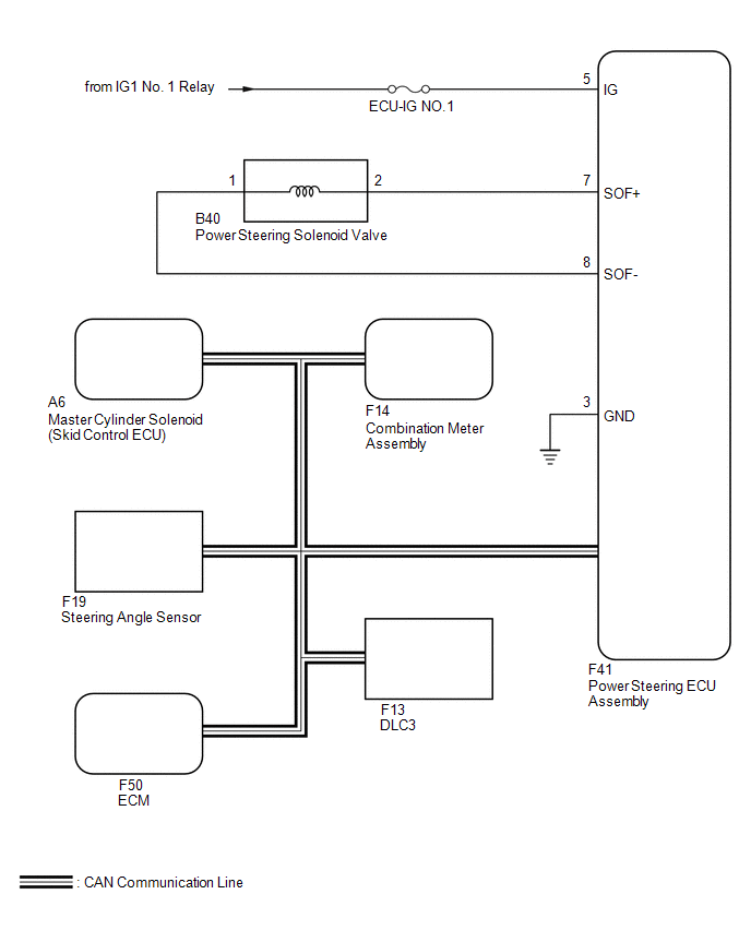
SYSTEM DIAGRAM
 Parts Location
PARTS LOCATION
ILLUSTRATION
ILLUSTRATION
...
 How To Proceed With Troubleshooting
CAUTION / NOTICE / HINT
HINT:
*: Use the Techstream.
PROCEDURE
1.
VEHICLE BROUGHT TO WORKSHOP
NEXT
...
Other materials about Toyota 4Runner:
Installation
INSTALLATION
CAUTION / NOTICE / HINT
HINT:
A bolt without a torque specification is shown in the standard bolt chart (See
page ).
PROCEDURE
1. INSTALL PINTLE HOOK SUPPORT TUBE SUB-ASSEMBLY (w/ Pintle Hook)
2. INSTALL REAR BUMPER UPPER RETAINER LH
...
Door Side Airbag Sensor RH Initialization Incomplete (B1693/81,B1698/82)
DESCRIPTION
The circuit for the side collision sensor LH or RH (to determine deployment of
the front seat side airbag LH or RH and curtain shield airbag LH or RH) is composed
of the center airbag sensor, rear airbag sensor LH or RH and side airbag sensor ...
© 2016-2026 | www.to4runner.net

0.0064
0.0064