Toyota 4Runner: Terminals Of Ecu
TERMINALS OF ECU
 Text in Illustration
|
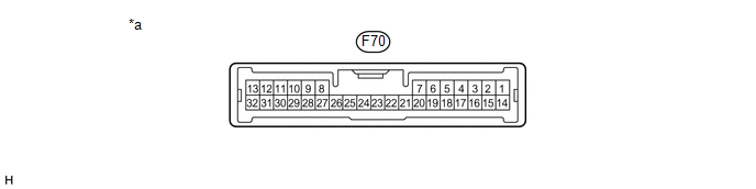
*a |
Component with harness connected (Stabilizer Control ECU) |
- |
- |
|
Terminal No. (Symbol) |
Wiring Color |
Terminal Description |
Condition |
Specified Condition |
|---|---|---|---|---|
|
F70-1 (SLAL) - Body ground |
LG - Body ground |
Stabilizer control solenoid valve output signal (for Upper Chamber) |
Ignition switch ON Vehicle stopped |
Below 1 V |
|
F70-3 (SLAU) - Body ground |
P - Body ground |
Stabilizer control solenoid valve output signal (for Lower Chamber) |
Ignition switch ON Vehicle stopped |
Below 1 V |
|
F70-6 (SGP1) - Body ground |
G - Body ground |
Pressure sensor ground |
Always |
Below 1 V |
|
F70-15 (SBP1) - Body ground |
R - Body ground |
Power source (Pressure sensor) |
Ignition switch ON |
4.75 to 5.25 V |
|
F70-17 (SOP1) - Body ground |
GR - Body ground |
Pressure sensor input signal |
Ignition switch ON |
0.4 to 4.6 V |
|
F70-22 (GND) - Body ground |
W-B - Body ground |
Ground |
Always |
Below 1 Ω |
|
F70-24 (IG) - Body ground |
B - Body ground |
Power source |
Ignition switch ON |
11 to 14 V |
|
F70-28 (CANL) - F70-29 (CANH) |
W - P |
CAN communication line |
Ignition switch off |
54 to 69 Ω |
 Problem Symptoms Table
PROBLEM SYMPTOMS TABLE
HINT:
Use the table below to help determine the cause of problem symptoms.
If multiple suspected areas are listed, the potential causes of the symptoms
are lis ...
 Diagnosis System
DIAGNOSIS SYSTEM
1. DIAGNOSIS SYSTEM
(a) Indicator light
(1) During vehicle stabilizer control operation, the KDSS indicator light comes
on when there is a malfunction in the KDSS.
NOTICE:
...
Other materials about Toyota 4Runner:
Only Wireless Control Function is Inoperative
DESCRIPTION
The door control receiver receives signals from the transmitter and sends these
signals to the main body ECU. The main body ECU then controls all the doors by sending
lock/unlock signals to each door.
WIRING DIAGRAM
CAUTION / NOTICE / HINT ...
Hitch
Trailer hitch assemblies have different weight capacities. Toyota recommends
the use of Toyota hitch/bracket for your vehicle. For details, contact your
Toyota dealer.
• If you wish to install a trailer hitch, contact your Toyota dealer.
• Use only a ...

0.0071