Toyota 4Runner: Vehicle Speed Signal Error (Test Mode DTC) (C2191/91)
DESCRIPTION
The tire pressure warning ECU receives a vehicle speed signal from the combination meter. This DTC is stored upon entering test mode and cleared when a vehicle speed signal of 20 km/h (12 mph) is detected for 3 seconds or more. This DTC is stored only in test mode.
|
DTC Code |
Detection Condition |
Trouble Area |
|---|---|---|
|
C2191/91 |
The test mode procedure is performed. |
|
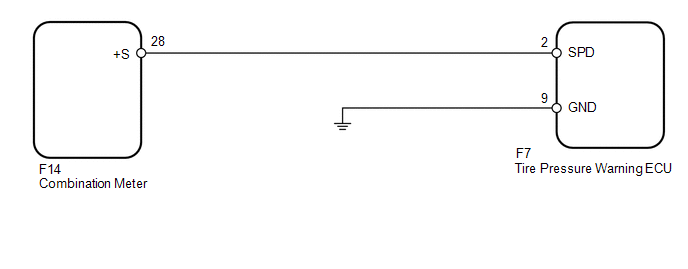
WIRING DIAGRAM
CAUTION / NOTICE / HINT
NOTICE:
- When replacing the tire pressure warning ECU, read the transmitter IDs stored in the old ECU using the Techstream and write them down before removal.
- It is necessary to perform registration of the transmitter IDs into
the tire pressure warning ECU after the ECU and/or the tire pressure warning
valve and transmitter has been replaced (See page
.gif) ).
).
PROCEDURE
|
1. |
READ VALUE USING TECHSTREAM (VEHICLE SPEED) |
(a) Turn the ignition switch off.
(b) Connect the Techstream to the DLC3.
(c) Turn the ignition switch to ON.
(d) Turn the Techstream on.
(e) Enter the following menus: Chassis / Tire Pressure Monitor / Data List.
(f) Check that the values indicated on the Techstream and on the combination meter are the same.
Tire Pressure Monitor|
Tester Display |
Measurement Item/Range |
Normal Condition |
Diagnostic Note |
|---|---|---|---|
|
Vehicle Speed |
Vehicle speed/ min.: 0 km/h (0 mph) max.: 255 km/h (158 mph) |
Almost same as actual vehicle speed |
The speed indicated on the combination meter. |
OK:
Vehicle speed indicated on the Techstream and on the combination meter are the same.
| OK | .gif) |
USE SIMULATION METHOD TO CHECK |
|
.gif)
|
2. |
INSPECT TIRE PRESSURE WARNING ECU (SPD SIGNAL) |
(a) Disconnect the F7 ECU connector.
(b) Jack up the vehicle.
(c) Move the shift the lever to N.
(d) Turn the ignition switch to ON.
|
(e) Check the waveform of the ECU connector using an oscilloscope while turning any of the wheels slowly. OK:
HINT: The wavelength becomes shorter as the wheels are rotated faster. Text in Illustration
|
|
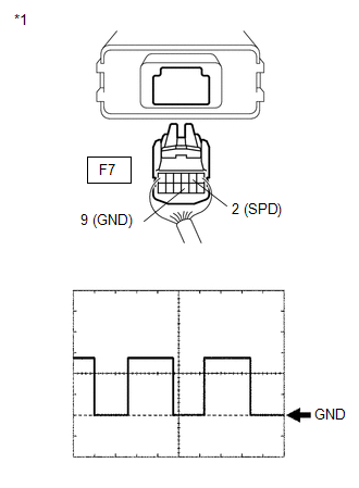
| OK | |
REPLACE TIRE PRESSURE WARNING ECU |
|
|
3. |
CHECK HARNESS AND CONNECTOR (ECU - COMBINATION METER) |
(a) Disconnect the F7 ECU connector.
(b) Disconnect the F14 meter connector.
(c) Measure the resistance according to the value(s) in the table below.
Standard Resistance:
|
Tester Connection |
Condition |
Specified Condition |
|---|---|---|
|
F7-2 (SPD) - F14-28 (+S) |
Always |
Below 1 Ω |
|
F7-2 (SPD) - Body ground |
Always |
10 kΩ or higher |
| OK | |
GO TO METER/GAUGE SYSTEM (HOW TO PROCEED WITH TROUBLESHOOTING) |
| NG | |
REPAIR OR REPLACE HARNESS OR CONNECTOR |
 Transmitter ID1 Operation Stop (C2111/11-C2115/15)
DESCRIPTION
The tire pressure warning valve and transmitters installed in the tire and wheel
assemblies measure the tire pressures of the tires. The measured values are transmitted
to the tire pr ...
 Tire Pressure Warning Light Circuit
DESCRIPTION
If the tire pressure warning ECU detects a disconnected connector or an open
circuit between the tire pressure warning ECU and combination meter, the tire pressure
warning light turns ...
Other materials about Toyota 4Runner:
Components
COMPONENTS
ILLUSTRATION
ILLUSTRATION
ILLUSTRATION
ILLUSTRATION
ILLUSTRATION
ILLUSTRATION
ILLUSTRATION
ILLUSTRATION
ILLUSTRATION
ILLUSTRATION
...
Front Axle Hub Bolt
Components
COMPONENTS
ILLUSTRATION
Replacement
REPLACEMENT
CAUTION / NOTICE / HINT
HINT:
Use the same procedure for the RH and LH sides.
The procedure listed below is for the LH side.
PROCEDURE
1. REMOVE FRONT WHEEL
2. REMOVE ...

0.0258