Toyota 4Runner: Installation
INSTALLATION
PROCEDURE
1. INSTALL REAR WIPER MOTOR AND BRACKET ASSEMBLY
|
(a) Attach the 2 guides and temporally install the rear wiper motor and bracket assembly with the 3 bolts. |
|
.png)
(b) Tighten the 3 bolts.
Torque:
5.5 N·m {56 kgf·cm, 49 in·lbf}
(c) Connect the connector.
2. INSTALL REAR WIPER ARM AND BLADE ASSEMBLY
|
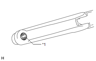
(a) Clean the wiper arm serrations. Text in Illustration
|
|
|
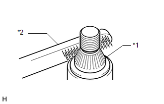
(b) Clean the wiper pivot serrations with a wire brush. Text in Illustration
|
|
(c) Operate the rear wiper and stop the rear wiper motor at the automatic stop position.
HINT:
The wiper motor does not operate if the back door and back door glass are not closed.
|
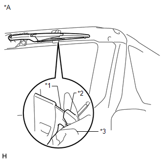
(d) With the rear wiper blade and linear wiper step in the positions shown in the illustration, install the rear wiper blade assembly with the nut. Torque: 5.5 N·m {56 kgf·cm, 49 in·lbf} Text in Illustration
HINT: Hold the arm hinge down by hand while tightening the nut. |
|
|
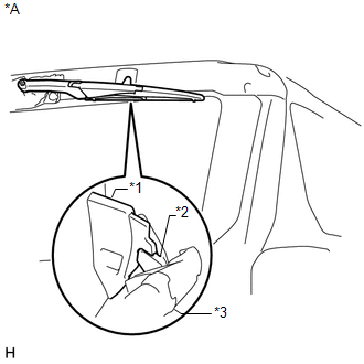
(e) Place the rear wiper blade assembly in the automatic stop position. Text in Illustration
|
|
3. INSTALL REAR SPOILER SUB-ASSEMBLY
.gif)
4. INSTALL REAR NO. 1 SPOILER COVER
5. CONNECT CABLE TO NEGATIVE BATTERY TERMINAL
NOTICE:
When disconnecting the cable, some systems need to be initialized after the cable
is reconnected (See page ).
 Inspection
INSPECTION
PROCEDURE
1. INSPECT REAR WIPER MOTOR AND BRACKET ASSEMBLY
(a) Check the wiper intermittent operation.
(1) Connect the positive (+) lead of the battery to terminal 5 (L) an ...
 Rear Wiper Rubber
Components
COMPONENTS
ILLUSTRATION
Replacement
REPLACEMENT
PROCEDURE
1. REMOVE REAR WIPER BLADE
(a) Apply protective tape to the areas shown in the illustration.
Text in Ill ...
Other materials about Toyota 4Runner:
Setting up a Bluetooth® enabled portable player
Registering a portable player in the Bluetooth® audio system allows the
system to function. The following functions can be used for registered portable
players:
Functions and operation procedures
Press and hold until “BT AUDIO”
is displayed.
Pr ...
Weight limits
• The gross trailer weight must never exceed the TWR described in the table.
• The gross combination weight must never exceed the GCWR described in the
table.
• The gross vehicle weight must never exceed the GVWR indicated on the
Certification ...

0.0082