Toyota 4Runner: Theft Deterrent System Communication Line High Fixation (B279A)
DESCRIPTION
If the communication line (EFIO-IMI) to the ID code box is stuck on HI output, the ECM stores this DTC.
|
DTC Code |
DTC Detection Condition |
Trouble Area |
|---|---|---|
|
B279A |
The communication line (EFIO-IMI) between the ECM and the ID code box is stuck on HI output. |
|
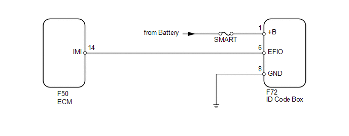
WIRING DIAGRAM
CAUTION / NOTICE / HINT
NOTICE:
- When the ID code box is replaced, refer to Registration (See page
.gif) ).
). - Inspect the fuses for circuits related to this system before performing the following inspection procedure.
PROCEDURE
|
1. |
CLEAR DTC |
(a) Clear the DTCs (See page ).
|
.gif)
|
2. |
CHECK FOR DTC |
(a) Check for DTCs (See page ).
HINT:
If DTCs other than DTC B279A are output, troubleshoot those DTCs first.
Result|
Result |
Proceed to |
|---|---|
|
DTC B279A is not output |
A |
|
DTC B279A and other DTCs are output |
B |
|
DTC B279A is output |
C |
| A | .gif) |
USE SIMULATION METHOD TO CHECK |
| B | |
Go to DIAGNOSTIC TROUBLE CODE CHART |
|
|
3. |
CHECK HARNESS AND CONNECTOR (ID CODE BOX - ECM) |
(a) Disconnect the F72 box connector.
(b) Disconnect the F50 ECM connector.
(c) Measure the resistance according to the value(s) in the table below.
Standard Resistance:
|
Tester Connection |
Condition |
Specified Condition |
|---|---|---|
|
F72-6 (EFIO) - F50-14 (IMI) |
Always |
Below 1 Ω |
|
F72-6 (EFIO) or F50-14 (IMI) - Body ground |
Always |
10 kΩ or higher |
| NG | |
REPAIR OR REPLACE HARNESS OR CONNECTOR |
|
|
4. |
CHECK ID CODE BOX (OUTPUT) |
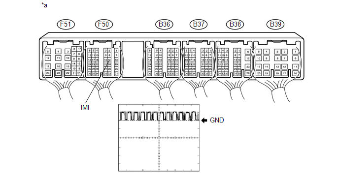
(a) Using an oscilloscope, check the waveform.
 Text in Illustration
|
*a |
Component with harness connected (ECM) |
- |
- |
|
Item |
Content |
|---|---|
|
Tester Connection |
F50-14 (IMI) - Body ground |
|
Tool Setting |
10 V/DIV., 100 ms./DIV. |
|
Condition |
Engine switch on (IG) |
OK:
Waveform is output normally (refer to illustration).
| OK | |
REPLACE ECM |
|
|
5. |
CHECK HARNESS AND CONNECTOR (ID CODE BOX - BATTERY AND BODY GROUND) |
|
(a) Disconnect the F72 box connector. |
|
(b) Measure the voltage according to the value(s) in the table below.
Standard Voltage:
|
Tester Connection |
Condition |
Specified Condition |
|---|---|---|
|
F72-1 (+B) - Body ground |
Always |
11 to 14 V |
(c) Measure the resistance according to the value(s) in the table below.
Standard Resistance:
|
Tester Connection |
Condition |
Specified Condition |
|---|---|---|
|
F72-8 (GND) - Body ground |
Always |
Below 1 Ω |
|
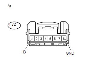
*a |
Front view of wire harness connector (to ID Code Box) |
| NG | |
REPAIR OR REPLACE HARNESS OR CONNECTOR |
|
|
6. |
REPLACE ID CODE BOX |
(a) Replace the ID code box (See page ).
|
|
7. |
REGISTER RECOGNITION CODES |
(a) Register the recognition codes in the ECUs (See page
).
|
|
8. |
REGISTER ECU COMMUNICATION ID |
(a) Register the ECU communication ID (See page
).
|
|
9. |
CLEAR DTC |
(a) Clear the DTCs (See page ).
|
|
10. |
CHECK FOR DTC |
(a) Check for DTCs (See page ).
OK:
DTC B279A is not output.
| OK | |
END (ID CODE BOX IS DEFECTIVE) |
| NG | |
REPLACE ECM |
 Dtc Check / Clear
DTC CHECK / CLEAR
HINT:
When using the Techstream with the engine switch off to troubleshoot:
Connect the Techstream to the vehicle and turn a courtesy light switch on
and off at 1.5 ...
 Theft Deterrent System Presence Detection (B279C)
DESCRIPTION
If an ECM that is incompatible with the engine immobiliser system is installed,
the ECM stores this DTC.
DTC Code
DTC Detection Condition
Trouble Area
...
Other materials about Toyota 4Runner:
Four-wheel drive system (part-time 4WD models)
Use the front-wheel drive control lever or switch to select the following
transfer modes:
Type A
The four-wheel drive indicator comes on when H4, N or L4 mode is selected.
1. H2 (high speed position, two-wheel drive)
Use this for normal driving on dry ...
Cursor or Map Rotates when Vehicle Stopped
PROCEDURE
1.
CHECK CONDITION
(a) Check with the customer if the vehicle has been turned by a turntable.
OK:
Vehicle has not been turned by a turntable.
HINT:
If the vehicle is turned on a turntable with ...

0.0237